Industry case
Electronic and electrical products R & D design and finite element analysis, including chip semiconductor, automotive electronics, 3C electronics, household appliances R & D design and CAE simulation analysis.
Practical experience of finite element analysis in electronic and electrical industry
The composition of electronic and electrical products is generally more complex, to achieve some specific research and development goals need to solve a large number of engineering problems. With the maturity of modern CAE simulation technology, enterprises can completely combine this advanced R & D means with traditional test and design experience to form complementary, so as to enhance the R & D design ability, effectively guide the R & D design of new products, save product development costs, shorten the development cycle, and greatly improve the market competitiveness of enterprises.
Electronic appliance drop simulation
☑️ Drop analysis of whole machine with package ☑️ drop analysis of bare machine ☑️ palletizer drop analysis ☑️ Application scenario collision analysis
Case 1: Laptop drop simulation
The fall of a laptop computer is a nonlinear complex dynamic response caused by a violent collision dynamic load in a very short period of time, which belongs to a transient dynamic process. It is used to calculate the structural dynamics of the load with time. The speed, acceleration, displacement and force of the structure can all change with time. This case is about the policy analysis process of laptop corner drop.

Case 2: TV Drop (Packaging Cushioning Foam Material) With the rapid development of the global electronics industry, the design of electronic products is becoming increasingly refined and complex. Market competition requires that while the performance indicators of electronic products are greatly improved, they also need to be increasingly miniaturized. CAE simulation has a wide range of applications in the electronics industry, such as the drop of electronic products, the research and development and manufacturing of new electronic materials, and the design and evaluation of the sound field characteristics of audio equipment.

Structural strength analysis of electronic appliances
☑️ random vibration analysis ☑️ Machine structure analysis ☑️ circuit board structure analysis ☑️ device package structure analysis ☑️ package structure analysis
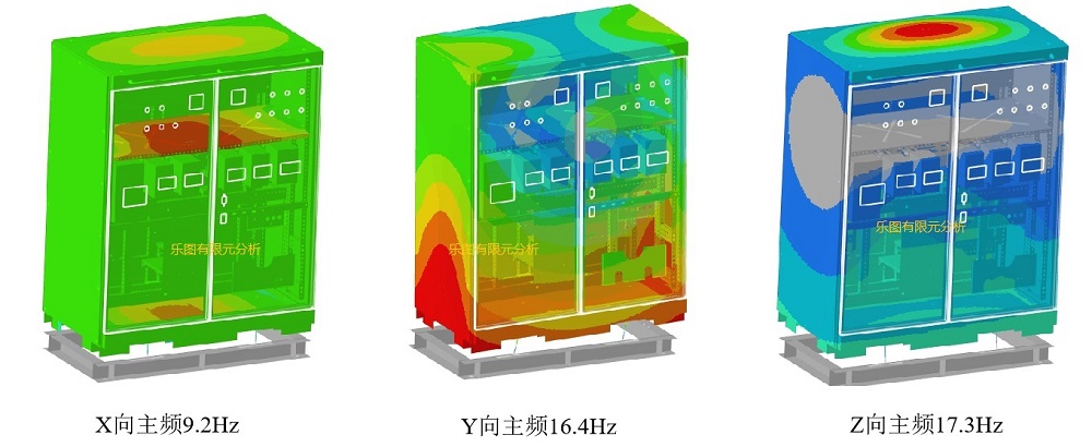
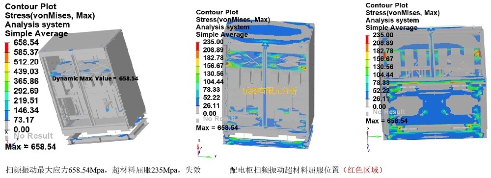
Case 1: Distribution box modal analysis and sweep vibration analysis
Modal analysis is a method to study the dynamic characteristics of structures, which is generally used in the field of engineering vibration. Among them, mode refers to the natural vibration characteristics of mechanical structure, and each mode has a specific natural frequency, damping ratio and mode mode.
Thermal simulation analysis of electronic appliances
Thermal simulation of electronic products, thermal analysis of chip packaging, EMC/EMI, etc., are very deep, complex and challenging topics in the field of electronics.
☑️ Heat flow analysis of complete machine ☑️ natural heat conduction, convection and radiation ☑️ natural thermosolid coupling ☑️ forced heat flow analysis ☑️ Analysis of thermal fluid flow of liquid cooled Radiator ☑️ temperature circulation stress analysis of solder joint
Case 1: Automotive electronic VIU chassis cooling simulation
Calculation parameters: Ambient temperature: 85 ° C Heat dissipation mode: natural heat dissipation Steady heat dissipation
Boundary conditions: natural convection condition; Is the open boundary condition; Zero equation turbulence model; Considering the influence of thermal radiation, in order to ensure the simulation accuracy: grid number: 81W
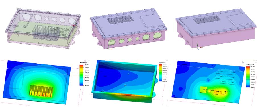
Conclusion: When the ring temperature is 85℃, the thermal risk of the main chip is small, and the minimum margin between the simulated junction temperature and the maximum allowable junction temperature is 8℃, which can meet the needs of use. Because the simulation is a natural convection environment, the environment is more stringent, and the thermal design margin is sufficient. In the actual DV chamber 85 high temperature test, the actual chip temperature will be lower due to the influence of wind;
Case 2: IT data center server heat dissipation simulation
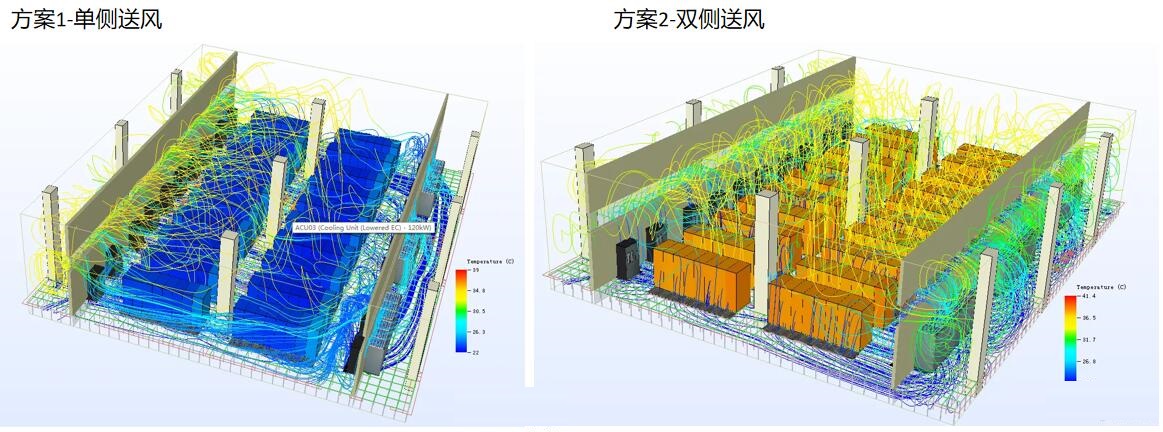

For the cooling simulation of electronic equipment, it provides a complete component model dedicated to electronic equipment. During the simulation, the thermal model is automatically simplified, and the heat consumption and air flow path inside the model are preserved. It is convenient to place the model into the cabinet or large system environment for larger scale cabinet or system level thermal analysis. Support hundreds of millions of grid scale, multi-core parallel computing solution is accurate, fast, efficient, robust, calculation rate of 5 million grid/hour. For the industry's largest commercial data center component inventory repositories, such as computer rooms and data centers, allowing large models to be solved at unprecedented speeds. The cooling systems analyzed include water-cooled, direct expansion, fresh air, direct and indirect evaporative cooling, including outdoor units, cooling towers, and chiller air flow organization analysis. It also involves O&M management, importing real-time DCIM monitoring data, and visualizing equipment room capacity. Now the analysis content has been expanded to electric vehicle thermal management, charging station thermal management, lighting system and more fields。
Case 3: Chip thermal simulation


FCBGA simulation condition 1: Package size :19*19mm, substrate thickness XXmm, heat dissipation copper block XX*XX*XXmm; Chip power consumption :XX W, size :XX*XXmm; The ambient temperature is set to XX℃ or XX℃. The model was placed in a closed test chamber of JEDEC standard and heat dissipation simulation analysis was performed. Heat dissipation cap + ambient temperature XX℃+TIM thermal conductivity XX W/m-k: As can be seen from the temperature distribution cloud diagram, when chip power consumption is XX W, the highest junction temperature is mainly concentrated at the chip, the highest junction temperature of DIE is 184.2℃, and the thermal resistance value is Rja=(Tj-Ta)/P=12.4℃ /W. Heat dissipating copper block + ambient temperature XX ℃+TIM thermal conductivity XX W/m-k: As can be seen from the temperature distribution cloud diagram, when chip power consumption is XX W, the highest junction temperature is mainly concentrated at the chip, the highest junction temperature of DIE is 261.4℃, and the thermal resistance value is Rja=(Tj-Ta)/P=17.1℃ /W.
Results: According to the simulation results, the maximum junction temperature of the chip is too high, and the chip is easy to be damaged. According to the JEDEC standard, the thermal resistance of the chip is within a reasonable range when the heat dissipation cap scheme is used, while the thermal resistance of the chip is high when the heat dissipation copper block scheme is used.
Case 4: SiP Thermal Simulation:
Simulation conditions: Package size :23*23mm, substrate thickness :XX mm, chip power consumption :XX W, size :XX*XX mm; The ambient temperature is set to XX ℃. The model was placed in a closed test chamber of JEDEC standard and heat dissipation simulation analysis was performed.

As can be seen from the temperature distribution cloud diagram, when the chip power consumption is xxW, the highest junction temperature is mainly concentrated at the chip, the highest junction temperature of DIE is 57.5℃, and the thermal resistance is Rjb=(Tj-Tb)/P=5.4℃ /W.
Results: According to the simulation results, the ambient temperature was XX ℃, the Rja was 13 ℃/W, the Rjb was 5.4℃/W, and the Rjc was 2.03℃/W. The thermal resistance value is small, which meets the design requirements.
Case 5: TEC thermal simulation analysis
In order to verify the heat dissipation effect of the design scheme and the durability analysis of the product, the heat dissipation effect of the semiconductor refrigeration system was simulated. The transient thermal simulation was carried out under six operating conditions respectively: 0℃ *min, 65 ℃ *min, -20℃ *min, 85 ℃ *min, -40 ℃ *min and 125 ℃ *min.


Temperature rise at 0 ° C: Socket board temperature cloud, the temperature in the central area is between 65.4 ° C and 65.6 ° C; Lower mode TEC temperature cloud image, temperature between 67.5℃~67.7℃;
The temperature cloud image of the upper die load indenter region is between 65.0℃ and 65.2℃. Temperature cloud image of the load area of the lower mold, the temperature is between 65.2℃ and 65.4 ℃
85 ℃ cooling:


The temperature in the domain ranges from -20 ℃ to -20.1℃, the temperature cloud image of the lower mold TEC ranges from -20 ℃ to -20.3 ℃, the temperature cloud image of the upper mold load indenter region, the temperature of the indenter in the core region ranges from -20.2℃ to -20.4℃. The temperature cloud image of the load area of the lower die shows that the temperature of the indenter in the core area is between -20℃ and -20.2℃.
Case 6: PCB version thermal simulation
The steady-state temperature distribution of the circuit board results in the circuit board shown above: includes three chips that generate heat during normal operation. As long as the power supply is connected to the board, one chip can remain energized, and the other two chips will periodically activate and disconnect energy at different times. Steady-state thermal analysis and transient thermal analysis were used to study the heat generated by these chips.

To provide customers with rich engineering CAE simulation services
CAE engineering simulation consulting, enterprise simulation software selection and product provision, high-performance simulation equipment construction, specialized customized development and platform construction and other special consulting services.
And in the industry has accumulated a wealth of simulation consulting experience and typical cases, to provide customers with project-based simulation consulting and service industry comprehensive solutions.
Understand the team backbone

Leto finite element has unique advantages in the following aspects
Professional finite element technical consulting team
The company gathers global industrial product experts, simulation technology experts, experts have more than ten years of engineering simulation experience, deep industry background, solid professional theoretical foundation and skilled software application skills, can effectively and professionally solve customers' practical engineering problems. The company's consulting experts are distributed throughout the country, and the local support ability for customer needs is strong.
Rich technical resources
Including the strong support of senior technical experts from foreign partners such as CADFEM and ANSYS, as well as the inheritance and development of CAE simulation, knowledge and experience, can provide world-class technical capabilities and engineering experience
Rich CAE/CAD simulation tools, R & D tools resources, wide range of professional
Including FEA, CFD, FSI, Multiphysics, MDO, multi-domain system simulation, etc., can jointly solve a variety of complex simulation problems.
Diversified service types
Including project undertaking, hardware and software selection and configuration, specialized customized secondary development, technical training, project navigation, personnel training, fixed-point technical support, etc., to maximize the benefit of customer investment.
Statement: This article is original from the official website of Le Tu wisdom, please indicate the source.
See more cases: Heat dissipation analysis Thermal Simulation Analysis Collision analysis Modal Analysis CFD Analysis Electromagnetic Field Simulation Analysis Drop analysis Fatigue analysis
I guess you may have the following questions right now:
- What can you do? How much does it cost?
- How long will it take? What do I need to do?
- What information needs to be provided?
- How was it After sale?
It is difficult to have a standard answer to the same question because everyone has different emphasis. Please fill in the form information or directly online contact, we will give you the most appropriate answer!


