Connector terminal temperature rise electrothermal coupling simulation analysis, electrothermal simulation analysis
Business Contents:
Simulation of Electro-thermal Coupling Temperature Rise, Finite Element Analysis, Electric Field Analysis / Magnetic Field Simulation Analysis, High-frequency / Low-frequency Electromagnetic Simulation for industries such as electronics, automobiles, and medical care.
Electro-thermal Coupling Simulation Cases:
1. Electronic Connector Terminal - Thermo-electric Coupling Temperature Rise Simulation Analysis - Contact Resistance and Temperature Rise Analysis
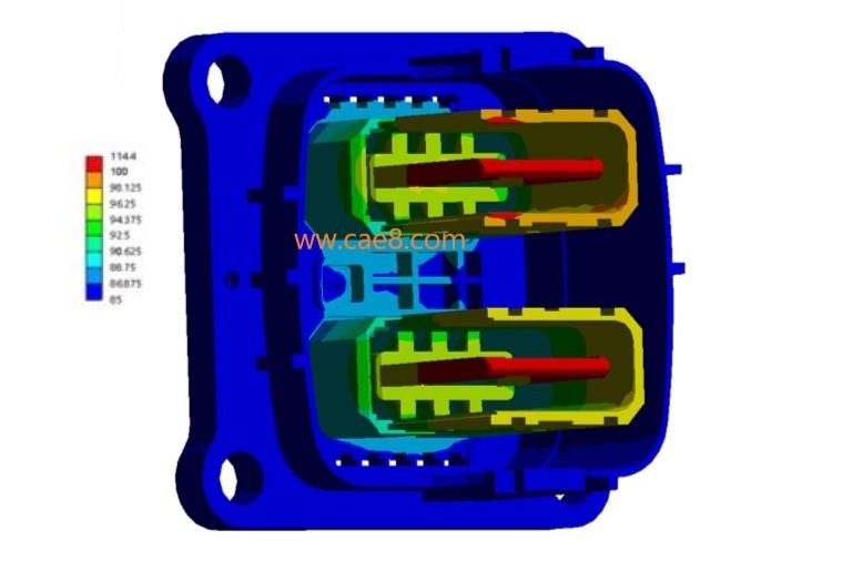
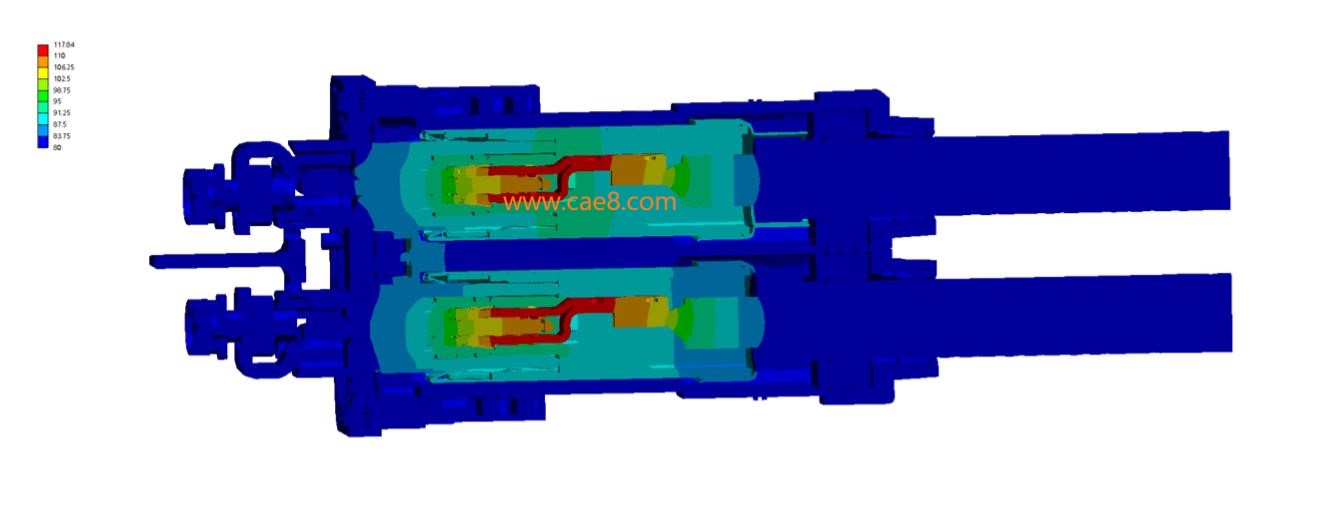
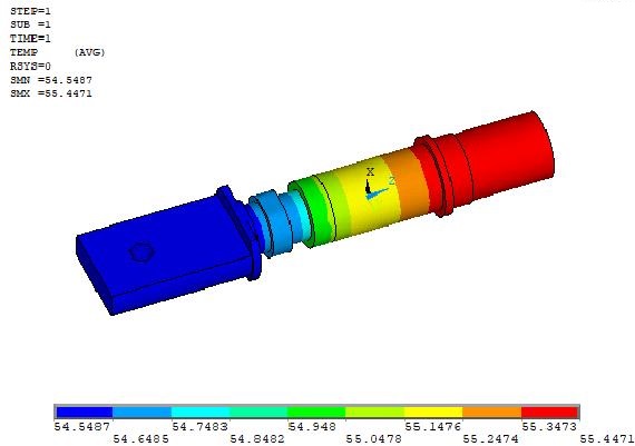
Overall Temperature Rise Distribution Contour Map :
Thermo-electric coupling analysis of the connector terminals of new energy vehicles. The following figure shows the overall temperature distribution contour map.
Connection Terminal Current Density Distribution Results :
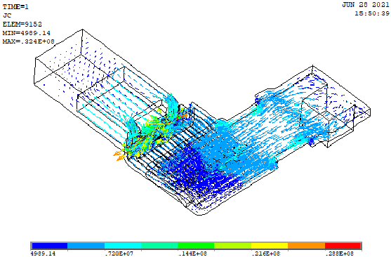
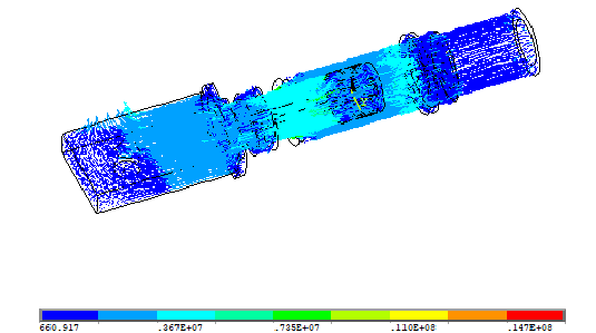
Connection Terminal Temperature Distribution Results:
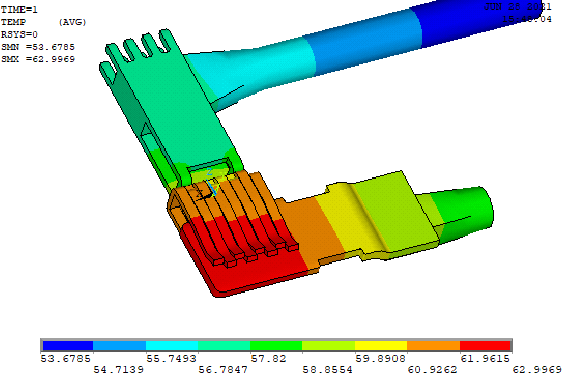
The above figure shows the multi-field coupling of connection resistance and temperature rise analysis: Connection resistance and temperature rise analysis is a multi-physics field coupling analysis. Considering the Joule heat of contact resistance, one simulation can solve the results of stress (including thermal stress), temperature distribution, and electric potential distribution.
2. Thermo-electric Coupling Simulation Analysis and Design Optimization of Laminated Busbars
Product Background:
The laminated busbar produced by an electronics manufacturer consists of flat conductors and an insulating film coated with adhesive. To reduce the resistance value of the circuit and enhance the thermal diffusion ability of the conductors, metals with high electrical conductivity and good thermal conductivity should be selected as conductor materials as much as possible. The conductors of laminated busbars are mainly made of copper.
Design Requirements:
Use the least number of conductors as possible to meet the current-carrying performance requirements of the busbar.
The conductors of laminated busbars are mainly made of copper, which means that the conductors account for the highest material cost. Therefore, in the optimization design process of the busbar, the least number of conductors should be used as possible to meet the current-carrying performance requirements of the busbar.
Design Scheme Comparison:
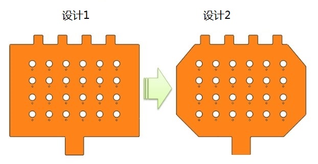
The following figure shows two schemes of laminated busbar plates for the original design scheme and the optimized design scheme.
Thermo-electric Coupling Analysis and Simulation Results:
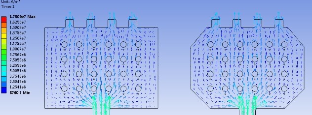
The following figure shows the current density vector distribution before and after optimization.
The following figure shows the heat generation power density distribution before and after optimization.
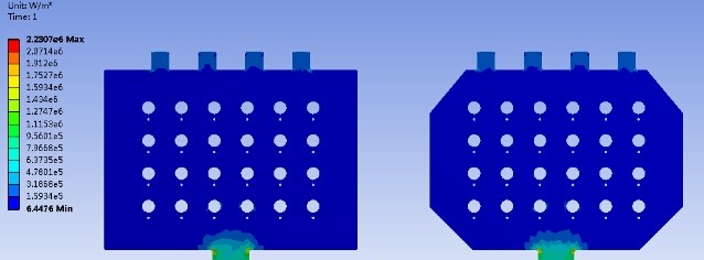
The following figure shows the steady-state temperature distribution before and after optimization.

Thermo-electric Coupling Simulation Value:
1. On the premise of saving copper materials, the current-carrying performance of the busbar has not been significantly weakened.
From the above electro-thermal coupling simulation analysis, it can be seen that along the direction of electron flow, there is no electron flow through the four corners. Through the optimized design of the laminated busbar plates, the ineffective areas can be removed.
2. Through the electro-thermal coupling simulation of the busbar, the flow situation of current (electrons) in the busbar conductors can be clearly seen, and even the heat generation power density and steady-state temperature distribution of the conductors can be obtained.
Declaration: This article is originally from the official website of Letu Zhizao. Please indicate the source when reprinting.
View more cases: Heat Dissipation Analysis Thermal Simulation Analysis Die Casting Mold Flow Analysis Modal Analysis CFD Analysis Electromagnetic Field Simulation Analysis Fatigue Analysis


Leto Intelligent Manufacturing Technology (Suzhou) Co., LTD
199 4191 2022
Business consulting/technical consulting/exchange advice
Scan code wechat consultation, 24 hours to look forward to your voice

