Air flow analysis simulation of IT data center machine room
Professional matters should be handled by professionals. We provide various CFD air flow analyses for clean spaces. Through the streamline cloud charts of air flow analysis, the gas flow direction can be clearly viewed, and it can be checked whether there are vortex areas or not, as well as the temperature results of air flow analysis. One can see the temperature conditions at various positions and whether heat can be dissipated evenly. Air flow simulation has already become an essential scientific technology for clean spaces in various industries.
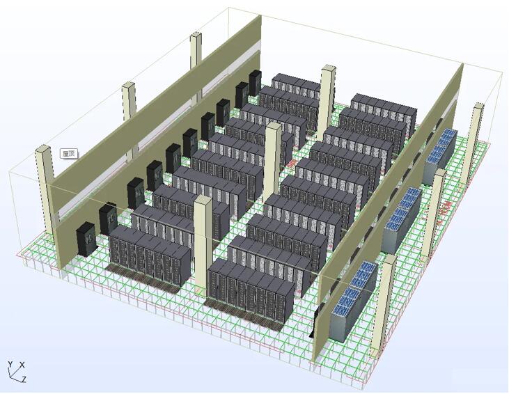
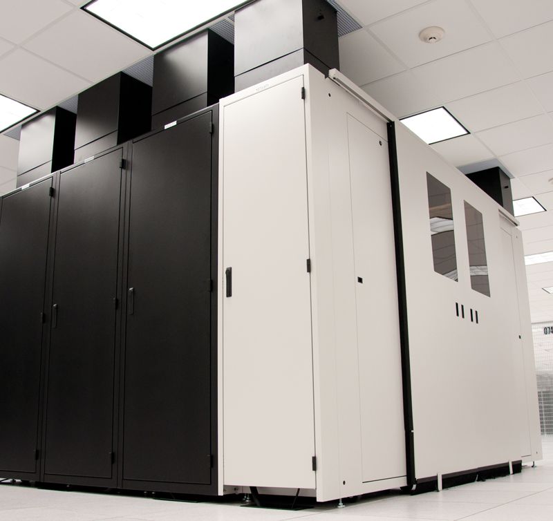
Case of Air Flow Analysis and Simulation:
Air Flow Analysis of a 4kW Computer Room without Aisle Enclosure
With the rapid development of the data center industry, the density of IT cabinets has been continuously increasing. The increase in the density of IT cabinets has led to increasingly strict requirements for air distribution in computer rooms. Regarding the air distribution in IT computer rooms, the current common practice is to divide cold and hot aisles. As for whether to enclose the cold and hot aisles or not, it has always been a controversial issue in the industry. After all, enclosing the cold and hot aisles will bring a significant increase in costs, and in the case of low density, the cost-effectiveness ratio may not be worth the effort.
1. Basic Information of Computer Room Air Flow Analysis:
1. The total area of the computer room is 600 m², and the area of the precision air-conditioning room is 160 m².
2. The floor height of the computer room is 6000 mm, the height of the raised floor is 800 mm, and there is no suspended ceiling.
3. The opening ratio of the floor air supply outlet is 50%, and it is adjusted to 60% at local unfavorable points.
4. The designed air supply temperature of the cold aisle in the IT computer room is 23 °C, and the designed return air temperature of the hot aisle is 35 °C.
5. The precision air conditioners are configured with 2N, with 6 in use and 6 as standby, and they usually operate at full load. The sensible cooling capacity is 131 KW, the air volume is 33000 m³/h, and the air supply temperature is set at 22 °C.
6. The air supply form of the air conditioner is under-floor air supply, and the return air form is the form of upper return air through side wall louvers.
7. The air distribution form is under-floor air supply of the raised floor + no enclosure of cold and hot aisles + upper return air through side walls.
2. Steps of Air Flow Analysis and Simulation
Air flow simulation analysis is a technology that uses computers to solve various partial differential equations of conservation control for fluid flow. Generally, air distribution simulation includes the following main steps: model establishment, condition setting, solver setting, numerical algorithm solution, and result visualization.
(1) Model Establishment: Firstly, a mathematical and physical model needs to be established. This usually involves obtaining data on the size and shape from actual equipment or buildings. This model can be a complete piece of equipment or a part of an equipment, as long as it contains all the important factors that affect air flow.
(2) Condition Setting: At this stage, CFD software will be used to set simulation conditions. The boundary conditions of the model need to be defined, such as inlets, outlets, walls, etc., and appropriate meshes need to be divided. The mesh is a mathematical structure used to discretize the model, which divides the continuous space into a series of discrete points. For complex models, this process may require certain knowledge of computational geometry.
(3) Solver Setting: When setting the solver, an appropriate CFD method (such as the finite volume method, the finite element method, etc.) needs to be selected. In addition, an appropriate turbulence model also needs to be selected because turbulence is an important and complex part in fluid dynamics.
(4) Numerical Algorithm Solution: After the above settings are completed, the simulation can be run for solution. The time required for this process depends on the size and complexity of the model, as well as the performance of the computer used.
(5) Result Visualization: After the solution is completed, CFD air flow analysis software usually generates a large amount of visual data, such as velocity fields, pressure fields, temperature fields, etc. These data need to be used to observe whether the air distribution is reasonable and whether it can meet the usage requirements, and to evaluate the design scheme accordingly.
(6) Design Optimization: Based on the above simulation results, we need to adjust the design scheme to optimize the air distribution, and continue to repeat the above steps for result verification. This process needs to be repeated for simulation and analysis until satisfactory results are obtained.
3. Simulation Results of Computer Room Air Flow Analysis:
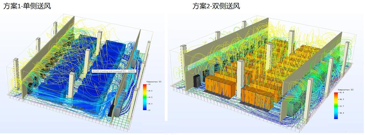
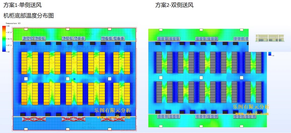
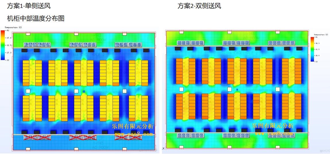
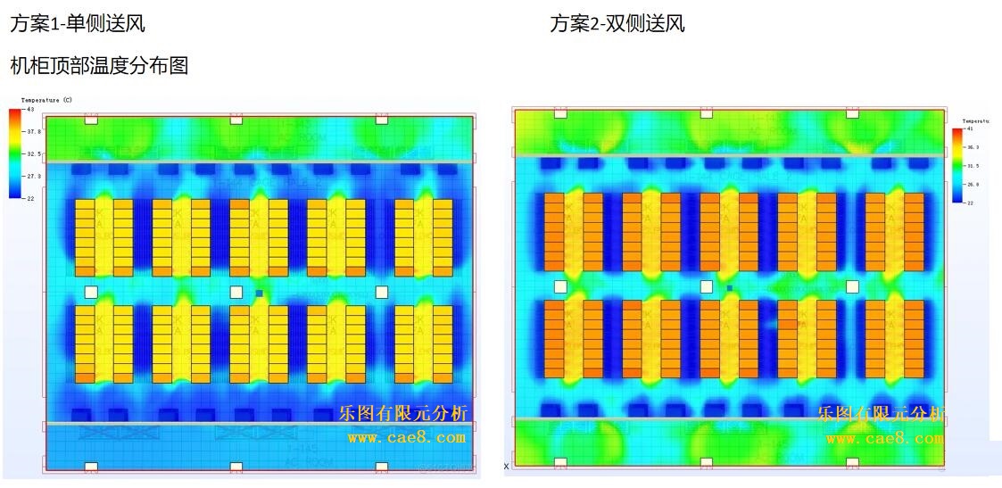
The following figures are the streamline cloud charts of air flow analysis for the two schemes, through which the gas flow direction can be clearly viewed and whether there are vortex areas can be checked.
Conclusion of Air Flow Simulation Analysis
1. Through air flow simulation analysis, for the IT cabinet setup without aisle enclosure, when adopting the same air supply floor layout as that with cold and hot aisle enclosure, both the bilateral full opening and unilateral air supply will result in uneven outlet air temperature of IT cabinets, and the uneven phenomenon is more serious in the unilateral air supply mode.
2. It can be considered to solve this problem by optimizing the layout of the air supply floor. However, in general cases, to solve all the problems that occur in the simulation, such as air mixing, uneven air intake of cabinets, and excessive temperature difference between the air inlet and outlet of cabinets, it is recommended to adopt the scheme of enclosing cold and hot aisles as much as possible.

Leto Intelligent Manufacturing Technology (Suzhou) Co., LTD
199 4191 2022
Business consulting/technical consulting/exchange advice
Scan code wechat consultation, 24 hours to look forward to your voice

