moldflow analysis Simulation of gas-assisted molding
Service Contents:
Gold-medal consultants, mold flow analysis for complex products, Moldex3D/Moldflow mold flow analysis, optimization of molding defects, material test fitting for UDB, sales of Moldex3D/Moldflow mold flow analysis software.
Application Value:
Many problems such as predicting air channel penetration, gas-assisted air streak effects, inability or unevenness of air channels to reach, and incomplete filling can be simulated and emulated for gas-assisted molding air channels through Moldflow mold flow analysis software or Moldex3D mold flow analysis software.
Application Cases:
Advantages of Gas-assisted Molding Process
1. Reduce the residual stress of products and prevent product deformation.
2. Solve and eliminate the problem of sink marks on the product surface, and it can be applied to products with large changes in thickness.
3. Reduce the clamping force of the injection molding machine and reduce the wear and tear of the molding machine.
4. Increase the working life of the injection molding machine.
5. Save plastic raw materials, with a saving rate of up to 30%.
6. Shorten the production and molding cycle time of products and improve production efficiency.
7. Reduce the pressure in the mold cavity, reduce the wear and tear of the mold and increase the service life of the mold.
8. For some plastic products, aluminum alloy materials can be used for molds.
9. Simplify the complicated design of products.
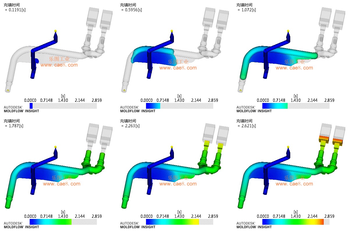
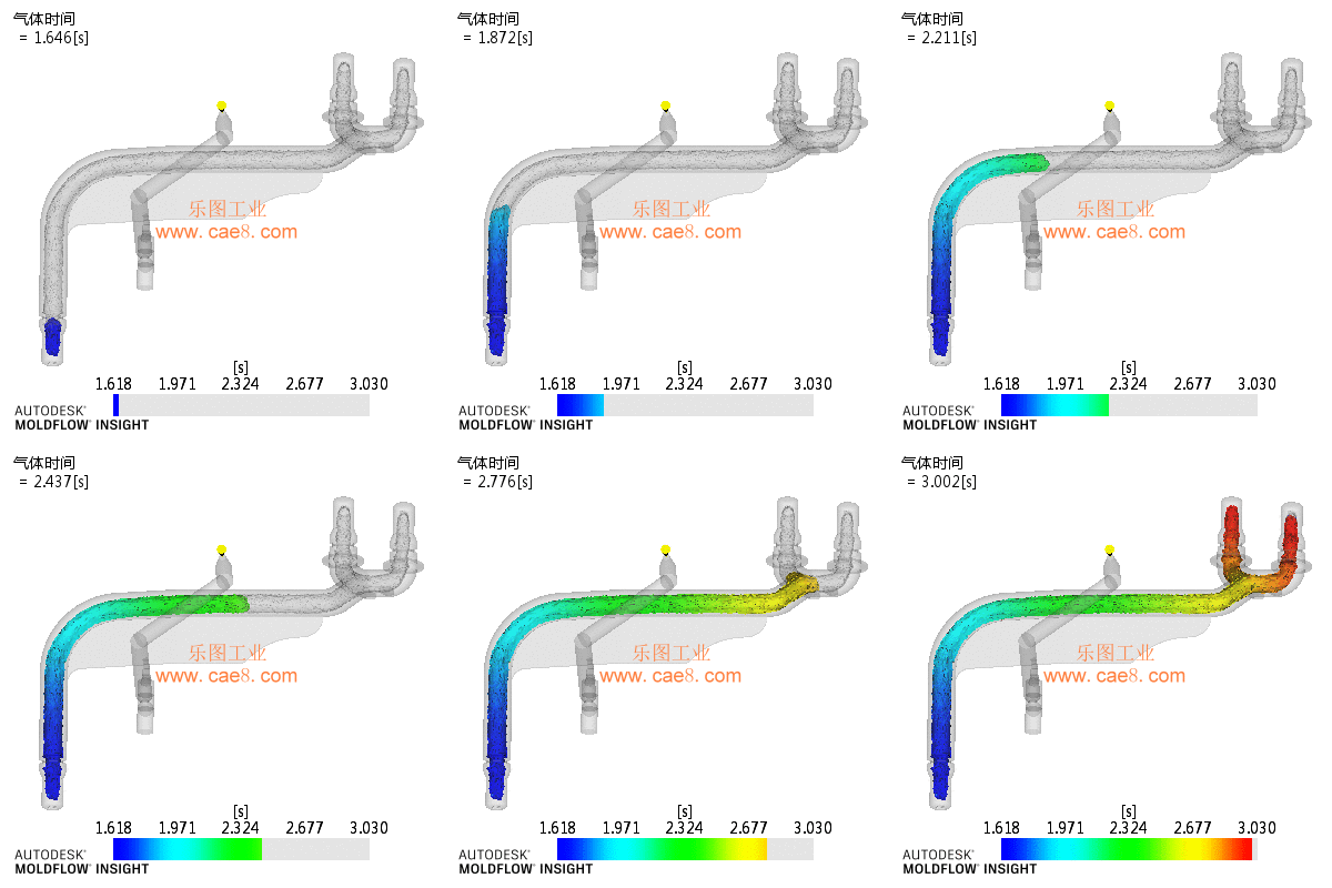
Simulation of gas-assisted molding for tee pipes (using Moldflow mold flow analysis software)
The results are as follows:


When the plastic is filled to 55%, it switches to the gas-assisted filling stage. The remaining cavity space will be filled by the excess solution at the cylinder. This is due to the pressure of nitrogen. Because of the flexibility of the gas, it can form a uniform and constant pressure along the cavity wall, which can keep the solidified layer on the cavity wall in a stable state. The unfrozen solution inside will be pushed forward by the air pressure until the entire cavity is filled. Then, a key question is, what should be done with the excess solution? This requires an overflow package to perform the storage function for the excess solution.
By using Moldflow mold flow analysis software and repeatedly debugging and simulating aspects such as gate position, air pressure, filling volume percentage, and filling speed, this effect is finally achieved. The air channel penetration is very good, with an overall uniform wall thickness distribution, and the thin-walled area around the gate is not penetrated by injection, which is a very crucial point.
Simulation of Gas-assisted Injection Molding for Chair Products (using Moldex3D Mold Flow Analysis Software)
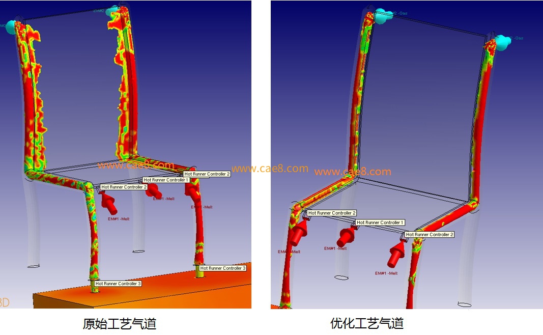
Optimize air channel parameters to improve air streak effects:
Use Moldex3D mold flow analysis software to optimize process parameters and improve gas air streak effects. In order to test whether the chairs produced with the new process parameters can meet the originally specified load, engineers obtain important molding simulation data through Moldex3D mold flow analysis software, including: gas hollowed-out areas, warped geometries, and fiber orientations, so as to improve the accuracy of FEM simulation. After performing FEM analysis in Abaqus, the results show that the new process parameters can manufacture chairs that meet the specified load, meet the lightweight requirements of the product, and also take into account the structural integrity.

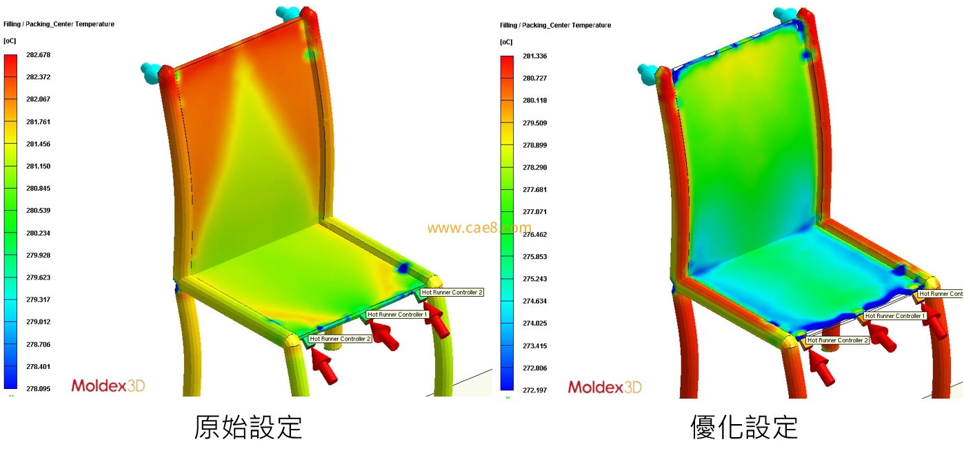
The analysis results of the original design show that the temperature difference between the center points of the thick and thin parts of the product at the time of gas-assisted switching is less than 2 °C. In other words, since the flow resistance of the thin and thick parts is similar, the gas easily enters the thin part (causing air streak effects). Similarly, when the temperature difference between the two regions is large, the gas will not enter the thin area. Therefore, increasing the gas delay, filling, and holding pressure time will help optimize the process.
Try to optimize the process with different combinations, including increasing the filling time to 6 seconds, the holding pressure time to 10 seconds, and the gas delay time to 15 seconds, etc. Figure 2 shows the simulation results after optimizing the parameters. The temperature difference between the center points of the thick and thin parts has changed to 7 to 10 °C, which means that the gas will not enter the thin part but will flow in the higher temperature (thick part) area because this area has a lower flow resistance.

Try to optimize the process with different combinations, including increasing the filling time to 6 seconds, the holding pressure time to 10 seconds, and the gas delay time to 15 seconds, etc. Figure 2 shows the simulation results after optimizing the parameters. The gas hollowed-out area has been successfully limited to the allowable area.

Leto Intelligent Manufacturing Technology (Suzhou) Co., LTD
199 4191 2022
Business consulting/technical consulting/exchange advice
Scan code wechat consultation, 24 hours to look forward to your voice

