Stress analysis of beam steel structure hoisting
Business Content:
Undertake various finite element analysis of shelves, mechanical analysis of steel structures, mechanical analysis of container lifting, stress analysis of pressure vessels, professional finite element simulation technical services for equipment in accordance with GB national standards, EU standards, and ASME (American Society of Mechanical Engineers) standards, serving industries such as petrochemical, transportation, civil construction, and nuclear power energy.
Get to Know the Core Team Members

Case 1 - Verification of Mechanical Analysis of Steel Structures
1. Overview
The mechanical analysis of steel structures mainly consists of supports, slide rails, lifting structures, and module structures. For the stress analysis of steel structure containers, since the non-standard structure cannot determine the bearing strength of the structure under different load conditions by conventional methods, the finite element analysis method is adopted to conduct a detailed finite element analysis and strength assessment on this structure.
2. Design Conditions
2.1 StressAnalysis Tools
The mechanical analysis and vibration characteristic analysis of steel structures adopt ANSYS finite element simulation software.
2.2 3D Structure Diagram
The overall structural design dimensions of the steel structure container are 2110x740x1869mm. The overall structure of the steel structure container is shown in Figure 2.1.
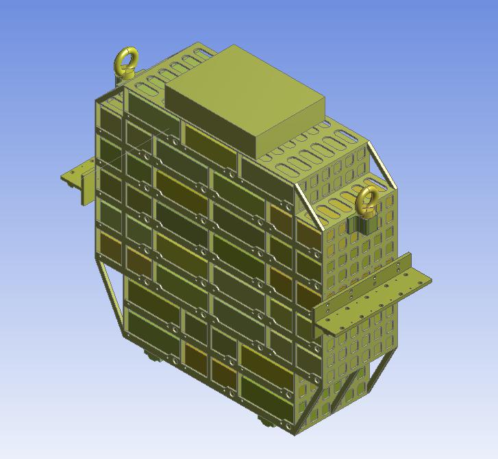
Figure 2.1 3D Overall Structure Diagram
2.3 Design Material Data
The main material of the structure is aluminum alloy 6061, and the mechanical property parameters of the material at the design temperature are shown in Table 2.1.
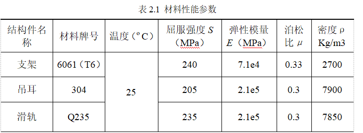
2.4 Calculation Conditions
According to the technical requirements of the high-pressure aluminum alloy support structure, the following analyses are carried out on the structure.
(1) Static state
(2) Lifting condition
(3) Vibration analysis is carried out according to the requirements of the technical documents, and the vibration conditions are shown in Table 2.2.
Table 2.2 Maximum Acceleration and Frequency

3. Finite Element Analysis Process
3.1 Static State
3.1.1 Solid Model
According to the design structure of the steel structure container, the model is appropriately simplified by ignoring some round hole chamfers that do not affect the stress distribution of the overall structure. The analysis model includes the upper cover, the bottom cover, and the internal electrical component structure. The created solid models are shown in Figures 3.1 to 3.3.
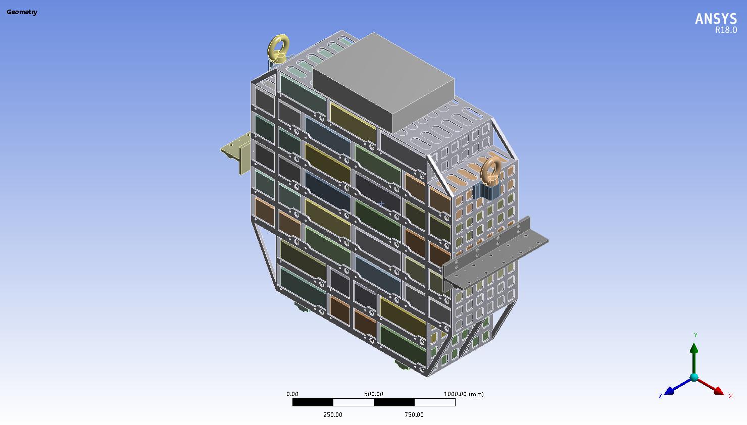
Figure 3.1 Solid Model of the Overall Structure
3.1.2 ANSYS Finite Element Model for Strength Analysis
The overall structure of the steel structure support is meshed by using the solid element solid186 in ANSYS Workbench, and a combined meshing method mainly based on hexahedrons and Sweep is adopted. The finite element model after meshing is shown in Figure 3.2. The total number of nodes in the finite element model is 2,360,262, and the number of elements is 620,115.

Figure 3.2 Finite Element Model of the Overall Structure
3.1.3 Boundary Conditions
In dealing with the displacement boundary conditions, fixed constraints are applied to the connection positions of the slide rails according to the installation situation of the overall structure. In the static state, the mechanical model for static analysis is shown in Figure 3.3.
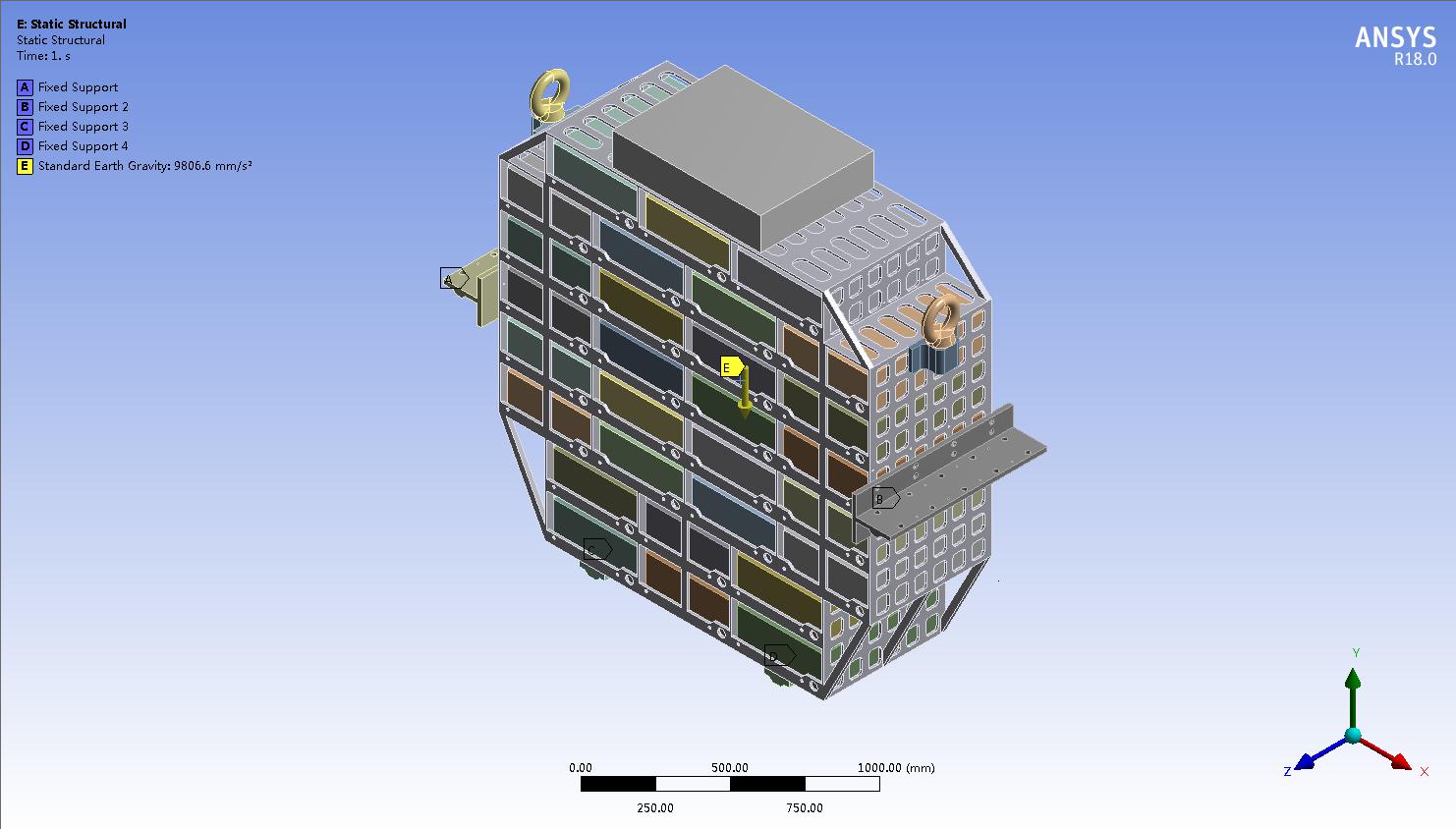
Figure 3.3 Mechanical Analysis Model of Steel Structures
3.1.4 Calculation Results of Stress Analysis of Steel Structures
Through static analysis of the overall structure of the steel structure container, the calculation results in the static state are obtained. The Von Mises stress analysis distribution cloud charts of the steel structure are shown in Figures 3.4 to 3.5.
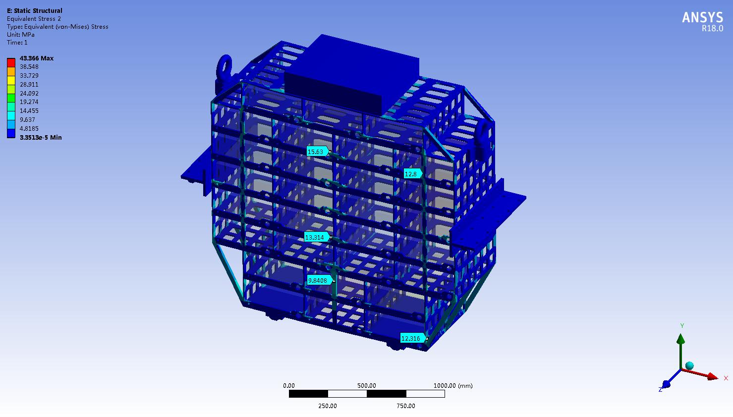
Figure 3.5 Von Mises Stress Cloud Chart of the Support Structure
It can be seen from Figure 3.4 that the maximum Von Mises stress value of the overall structure of the high-pressure aluminum alloy support in the static state is 43.37 MPa, which is much smaller than the yield strength of each material. Therefore, the strength of the overall structure in the static state is qualified.
3.2 Lifting State
3.2.1 Boundary Conditions
In the lifting state, the finite element model of the steel structure container is the same as that in the static state.
In dealing with the displacement boundary conditions, fixed constraints are applied to the lifting positions according to the lifting situation of the overall structure. Then, in the lifting state, the mechanical model for finite element analysis of the steel structure container is shown in Figure 3.6.
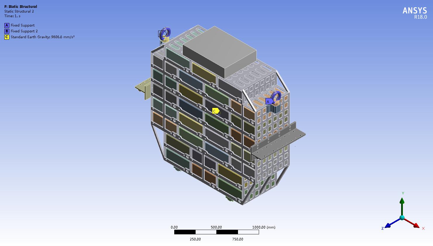
Figure 3.6 Mechanical Model of ANSYS Mechanical Analysis of Steel Structures
3.2.2 Calculation Results of ANSYS Stress Analysis
Through static analysis of the overall structure of the steel structure container, the calculation results in the lifting state are obtained. The Von Mises stress analysis distribution cloud charts are shown in Figures 3.7 to 3.8.
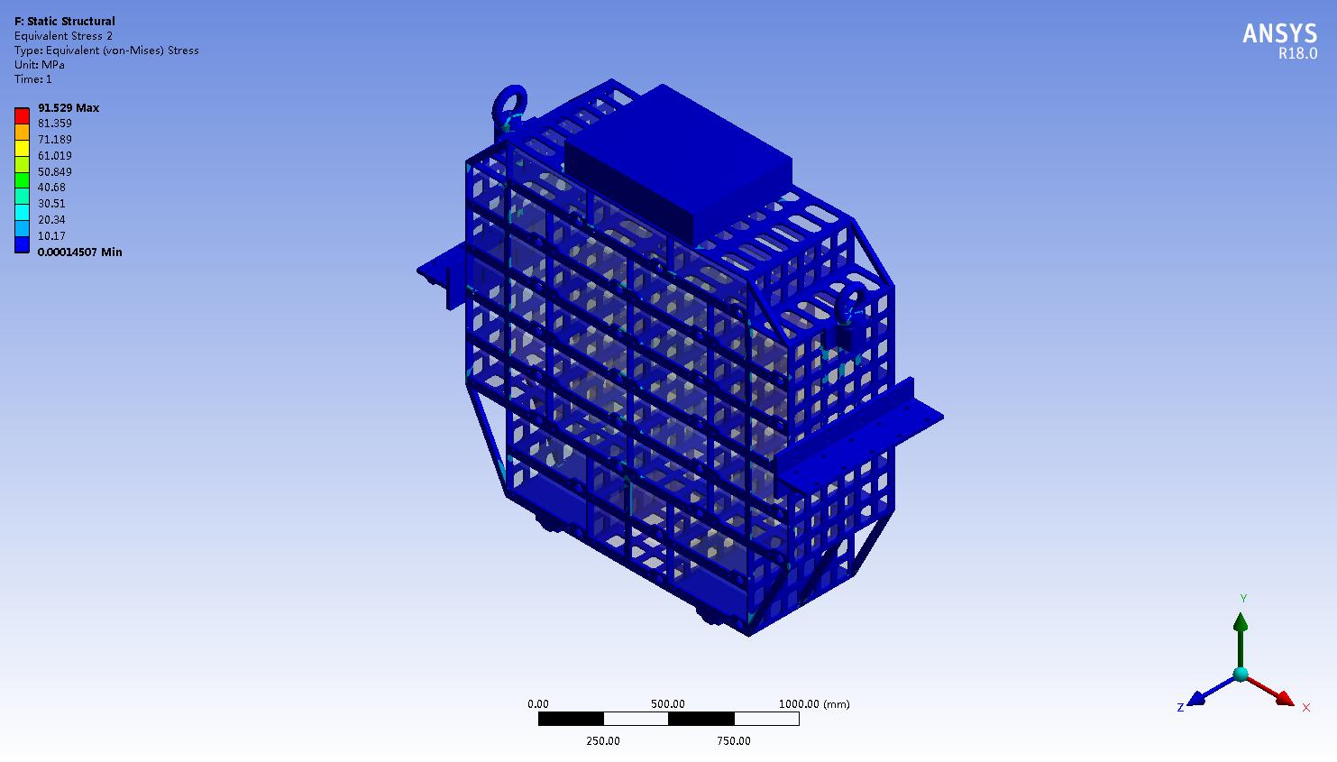
Figure 3.8 Von Mises Stress Cloud Chart of the Support Structure of Steel Structure Mechanical Analysis
It can be seen from Figure 3.4 that the maximum Von Mises stress value of the overall structure of the steel structure container in the static state is 91.53 MPa, which is much smaller than the yield strength of each material. Therefore, the strength of the overall structure in the lifting state is qualified.
3.3 Mechanical Analysis of Steel Structures - Modal Analysis
3.3.1 Boundary Conditions
In dealing with the displacement boundary conditions, fixed constraints are applied to the connection positions of the slide rails according to the installation situation of the overall structure. Its mechanical model is shown in Figure 3.3.
3.3.2 Calculation Results
Through modal analysis of the structure of the steel structure container, the first 5 natural vibration frequencies and the first 2 vibration modes are obtained. The frequency values are shown in Table 3.1.

The first-order to second-order modal vibration modes are shown in Figures 3.9 to 3.10.
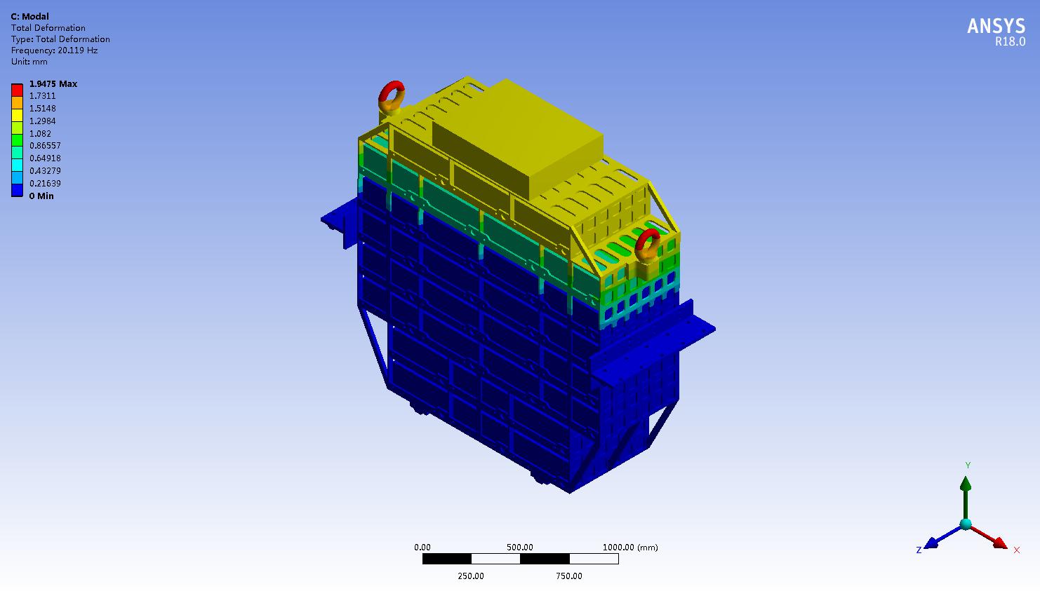
Figure 3.9 First-order Modal Vibration Mode Diagram
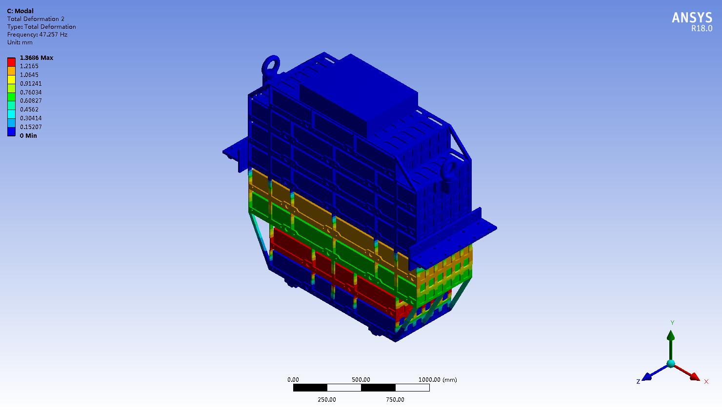
Figure 3.10 Second-order Modal Vibration Mode Diagram
It can be seen from Figures 3.9 to 3.10 that the amplitude of the upper module is relatively large at the first-order natural frequency, and the vibration of the lower module is obvious at the second-order natural frequency.
3.4 Harmonic Response Analysis
3.4.1 Boundary Conditions
In dealing with the displacement boundary conditions, fixed constraints are applied to the connection positions of the slide rails according to the installation situation of the overall structure. In dealing with the force boundary conditions, according to the vibration environment, the vibration acceleration shown in Table 2.2 is applied to the finite element model in the vertical direction of the structure. The mechanical model after loading is shown in Figure 3.11.

Figure 3.11 Mechanical Analysis Model of Steel Structures (Harmonic Response Analysis in the Vertical Direction)
3.4.2 Calculation Results of Harmonic Response in the Vertical Direction
In the frequency range from 16 Hz to 50 Hz, the excitation acceleration is the largest, and 50 Hz is relatively close to the second-order natural frequency of the structure. Therefore, the dynamic response of the structure at a frequency of 50 Hz can be extracted. The results of the harmonic response analysis are shown in Figures 3.12 to 3.13.
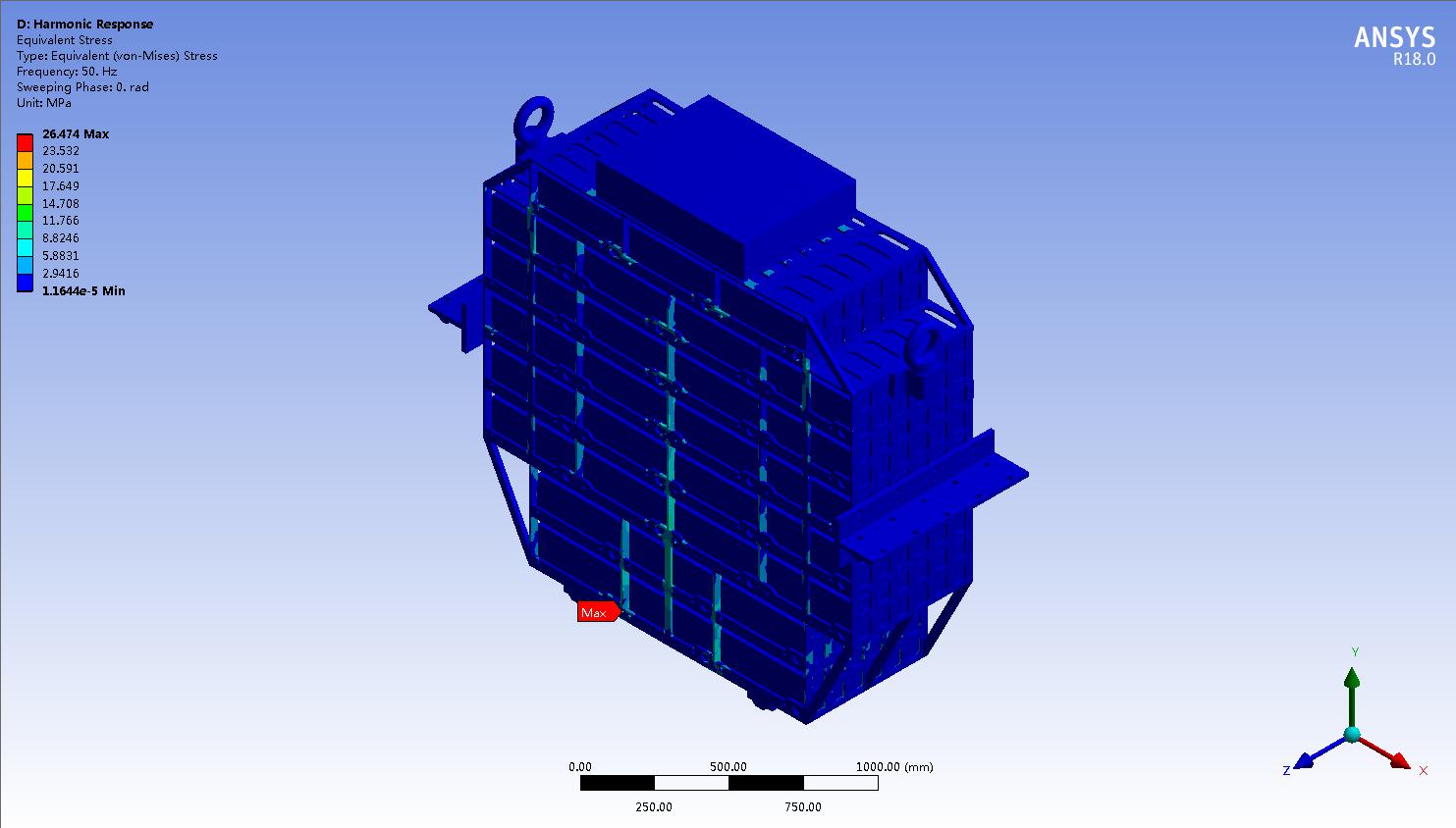
Figure 3.12 von-Mises Stress Cloud Chart of the Overall Structure at a Frequency of 50 Hz
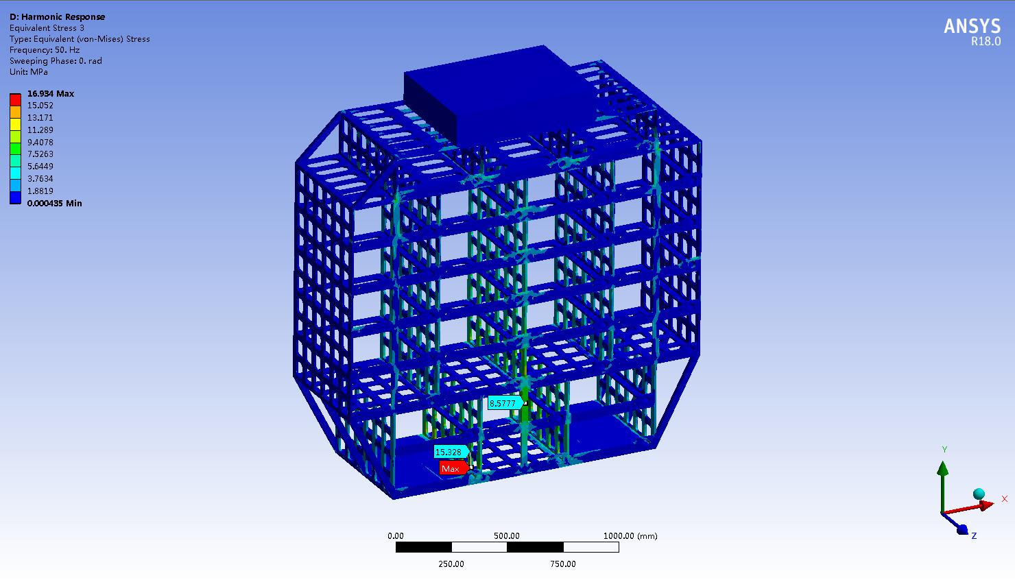
Figure 3.13 von-Mises Stress Cloud Chart of the Support at a Frequency of 50 Hz
It can be seen from Figure 3.12 that at a frequency of 50 Hz, the von-Mises stress value of the overall structure is located at the contact between the bottom module and the support, and the maximum stress value is 26.47 MPa, which is less than the allowable stress of the material and meets the structural strength requirements.
It can be seen from Figure 3.13 that at a frequency of 50 Hz, the maximum von-Mises stress value of the support is 16.93 MPa. The dynamic response result of this point within the excitation frequency range is extracted as shown in Figure 3.14.
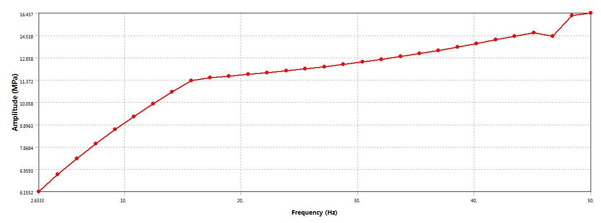
Figure 3.14 Curve of the Positive Stress in the Y Direction at the Point with the Maximum Stress Value Changing with the Frequency
It can be seen from Figure 3.14 that when the applied excitation frequency is close to the second-order natural frequency, the positive stress in the Y direction at the extraction point is relatively large, with a value of about 16.4 MPa, and the corresponding frequency is about 47.3 Hz. Then, under this frequency, the Von-Mises stress cloud charts of each component of the aluminum alloy support are shown in Figures 3.15 to 3.17.
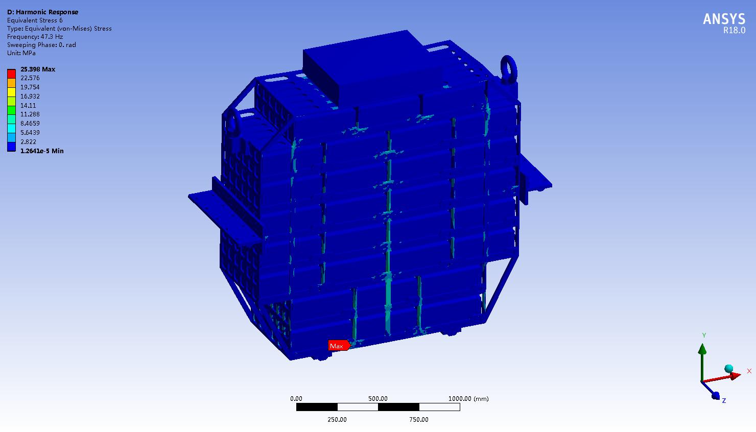
Figure 3.15 Von-Mises Stress Cloud Chart of the Overall Structure at a Frequency of 47.3 Hz
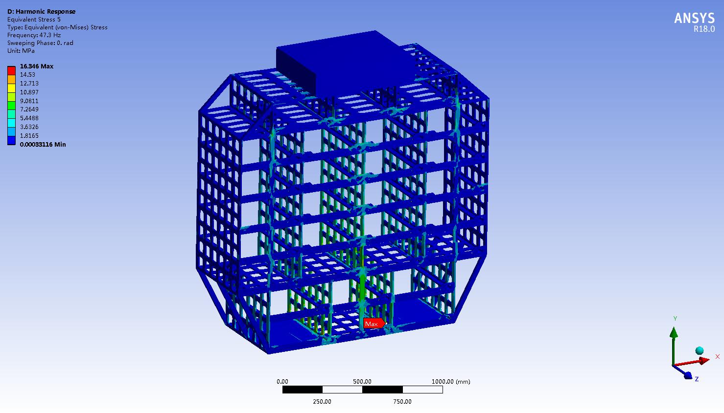
Figure 3.16 Von-Mises Stress Cloud Chart of the Support at a Frequency of 47.3 Hz
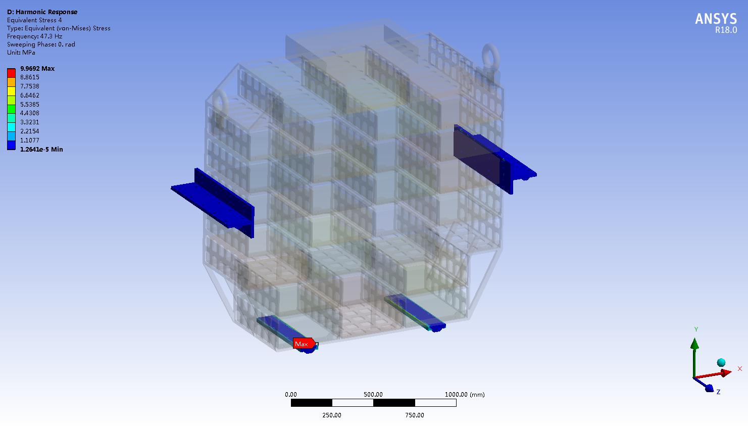
Figure 3.17 von-Mises Stress Analysis Cloud Chart of the Slide Rail at a Frequency of 47.3 Hz
It can be seen from Figure 3.15 that under the action of vertical vibration, the maximum von-mises stress value of the aluminum alloy support is located at the contact between the bottom module and the support, and its maximum value is 25.4 MPa.
It can be seen from Figure 3.16 that under the action of vertical vibration, the maximum von-mises stress value of the support is 16.35 MPa, which is less than the yield strength of the material, and the strength is qualified.
It can be seen from Figure 3.17 that under the action of vertical vibration, the maximum von-mises stress value of the slide rail is 10 MPa, which is less than the tensile strength of the material, and the strength is qualified.
4. Conclusions of Mechanical Analysis of Steel Structures
Through finite element analysis of mechanical analysis of steel structures under different working conditions, the following conclusions are obtained.
(1) The overall structural strength of the equipment meets the requirements under the static state and the lifting condition;
(2) The strength of the overall steel structure stress analysis of the equipment meets the requirements under the vertical vibration condition.
View More Cases
Declaration: This article is original from the official website of Letu Zhizao. Please indicate the source when reprinting.
View More Cases: Heat Dissipation Analysis Thermal Simulation Analysis Die Casting Mold Flow Analysis Modal Analysis CFD Analysis Electromagnetic Field Simulation Analysis Fatigue Analysis EMC Simulation

Leto Intelligent Manufacturing Technology (Suzhou) Co., LTD
199 4191 2022
Business consulting/technical consulting/exchange advice
Scan code wechat consultation, 24 hours to look forward to your voice

