Example of finite element calculation of bending flange of pressure vessel
In this example, a detailed stress analysis of the bent flange is carried out by using the finite element analysis method. And in accordance with JB4732-1995 "Steel pressure vessels - Analysis and design standard" (2005 confirmed) strength assessment.
Equipment design data sheet
A design condition
a. Main design parameters

b. The design and manufacturing standard of the pressure vessel is GB150.1 ~ 150.4-2011 Pressure Vessel. The method of local analysis and design is used to check, and the evaluation method is referred to JB4732-1995 "Steel pressure vessels - Analysis and design Standard" (confirmed in 2005).
Check GB150.1 ~ 150.4-2011 "Pressure vessel" : Material S31603 at the design temperature of 150℃, the allowable stress [σ]t =87MPa
c. The calculation conditions are as follows:

Note [1] : The selection of calculated pressure According to the provisions of JB4732-95, when calculating the combined stress intensity including the secondary stress intensity, the working load should be selected for calculation. In this report, the design load is selected for calculation, which is safe for the analysis results.
d. The mechanical property parameters of the material are shown in the following table:

Note [2] : The values of allowable stress and elastic modulus are from GB150.1 ~ 150.4-2011 Pressure Vessel.
Two structural analysis and mechanical model
1. Original size structure drawing
2. Solid model
3. Element selection of finite element simulation model
The structural parameters of the components and the dimensions of each component used in this analysis report, and the thickness used in the analysis and calculation do not include the corrosion margin, and the following analysis and evaluation are based on this parameter. A total of 168426 units and 393149 nodes were divided, and the specific grid division results are shown in Figure 3.
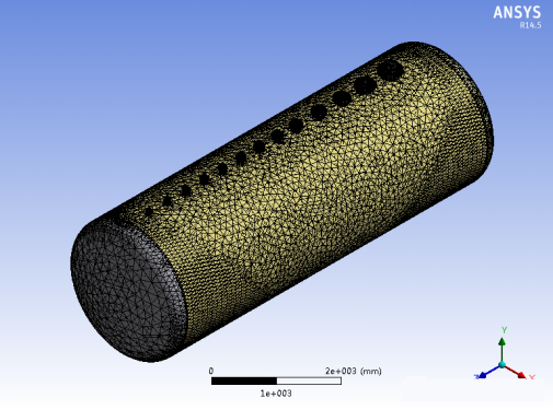
FIG. 3 Finite element analysis grid
4. Finite element analysis model analysis process
The analysis is done by importing material properties directly onto the analysis model, resulting in the following results.
4.1 Load of finite element analysis model
The internal pressure of the container is 0.55Mpa, and its loading situation is as follows:
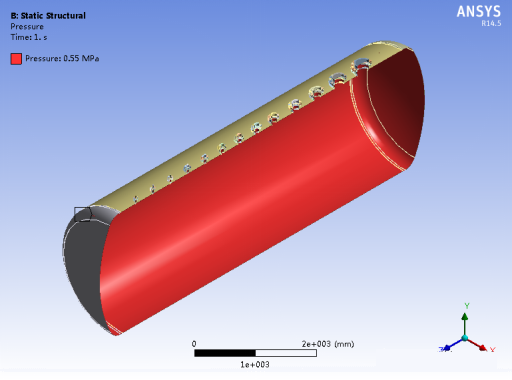
Figure 4 Model loading (section view)
5. Analysis results and stress intensity evaluation
5.1 Stress and displacement nephogram of flange
5.1.1 DN250 flange
The stress cloud diagram of the a.DN250 flange is shown in the following figure:
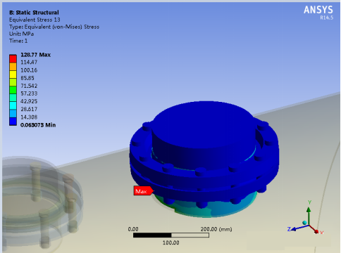
FIG. 5 The maximum equivalent stress of DN250 flange is 128.77MPa
b. The displacement cloud image of DN250 flange is shown in the following figure:
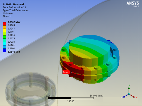
Figure 6 The maximum displacement of DN250 flange is 2.0362mm
5.1.2 DN200 Flange
The stress cloud diagram of the A.D200 flange is shown in the following figure:
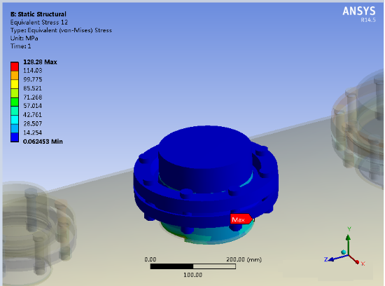
Fig.7 The maximum equivalent stress of DN200 flange is 128.28MPa
The displacement cloud image of the B.D200 flange is shown in the following figure

Figure 8 The maximum displacement of DN200 flange is 2.3995mm
5.1.3 DN150 Flange
The stress cloud diagram of a.DN150 flange is shown in the figure below:
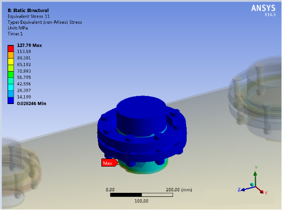
FIG. 9 The maximum equivalent stress of DN150 flange is 127.79MPa
B. DN150 flange displacement cloud image is shown in the following figure:

FIG. 10 The maximum displacement of DN150 flange is 2.5379mm
5.1.4 DN125 flange
The stress cloud diagram of a.DN125 flange is shown in the figure below:

Fig.11 The maximum equivalent stress of DN125 flange is 127.29MPa
B.d125 flange displacement cloud image is shown in the following figure:
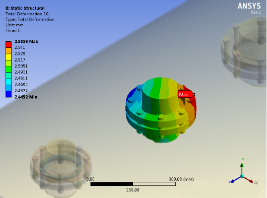
Fig.12 The maximum displacement of DN125 flange is 2.5529mm
Through the calculation of the above finite element model, the equivalent stress of each bent flange is less than 130.5MPa, which meets the requirements.

Leto Intelligent Manufacturing Technology (Suzhou) Co., LTD
199 4191 2022
Business consulting/technical consulting/exchange advice
Scan code wechat consultation, 24 hours to look forward to your voice

