Analysis of lifting force of container
Business Scope:
Undertake various finite element analysis of storage racks, calculations for stress analysis of steel structures, stress analysis of container lifting, stress analysis of pressure vessels, as well as professional finite element simulation technical services in accordance with GB national standards, EU standards, and ASME standards, serving industries such as petrochemical, transportation, civil construction, and nuclear power energy.
Case 1: Stress Analysis of Container Lifting (Showing Partial Content)
With the rapid development of China's economy, the construction of intelligent substations is increasing. As the basic equipment of substations, the demand for special containers is also growing day by day. Due to the wide variety and high degree of customization of special containers, higher requirements are put forward for the safety during transportation. The lifting operations of special containers are usually completed by lifting machinery, lifting tools, wire ropes, etc. Since the types, specifications, and masses of special containers are different, the lifting schemes adopted are also different. And as an essential tool in the lifting scheme, the selection of wire ropes directly affects the safety of the lifting process. Therefore, it is of great significance to analyze the lifting schemes of various special containers and the stress of their wire ropes.
1. Model Establishment
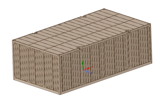
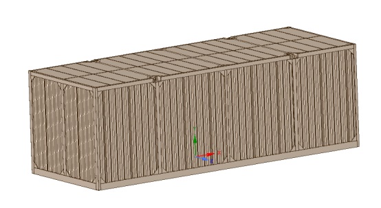
Import the three-dimensional model into SpaceClaim, remove the defects such as interference, chamfers, and interference existing in the model, and remove the parts irrelevant to structural calculation to obtain the finite element calculation model.
2. Material Selection
The specific parameters of materials are as follows:
| Material Model | E/ MPa | Poisson | Ρ/[t/mm³] | Re/ MPa Yield Limit |
Q345E |
206000 |
0.27 |
7.85e-9 |
345 |
E36 | 206000 | 0.27 | 7.85e-9 | 355 |
3. Finite Element Calculation Mesh Generation
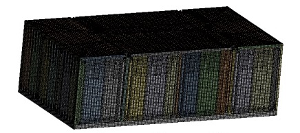
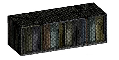
3.1 Mesh Generation for SIE-01 Container
The hexahedral mesh method is adopted for meshing. After meshing, there are 706,067 nodes and 174,783 elements.
4. Finite Element Static Analysis
4.1 SIE-01 Analysis
4.1.1 Load Addition - SIE-01
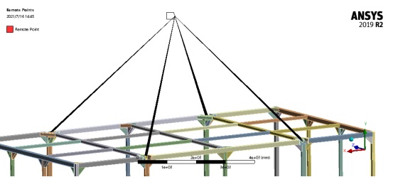
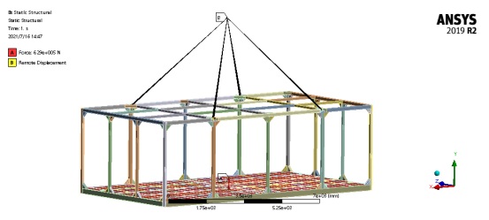
Establish a coordinate system at the position where the lifting point is inclined at 45 degrees, and establish the lifting point. Use the beam connection method for fixation. Load on the bottom surface of the model with a load of 62,900 kg.
4.1.2 Deformation Result - SIE-01
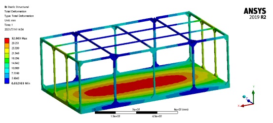
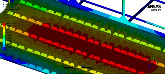
The maximum deformation is 32.9 mm, and the position is in the middle abdomen at the lower end of the model, meeting the stiffness requirements.
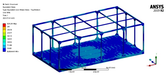
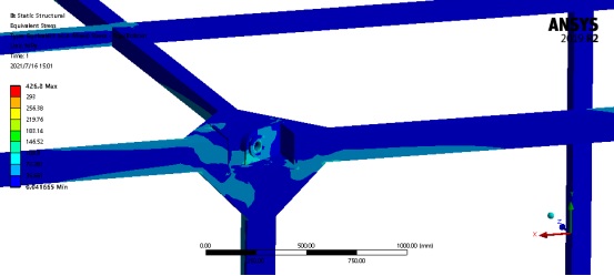
4.1.3 Stress Result - SIE-01
Adjust the stress scale to 0.85 times of RE, that is, 293 MPa. Except for the stress concentration points, the strength requirements are met.
4.2 SIE-02 Analysis
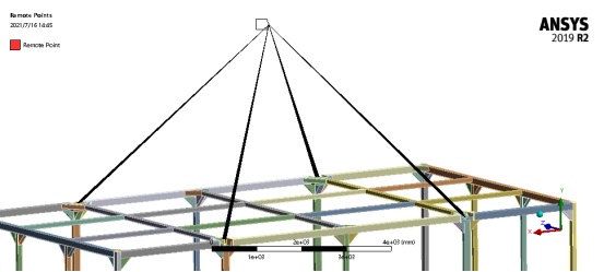
4.2.1 Load Addition - SIE-02
Establish a coordinate system at the position where the lifting point is inclined at 45 degrees, and establish the lifting point. Use the beam connection method for fixation. Load on the bottom surface of the model with a load of 56,500 kg.

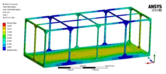
4.2.2 Deformation Result - SIE-02
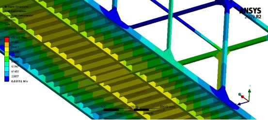
The maximum deformation is 18.5 mm, and the position is in the middle abdomen at the lower end of the model, meeting the stiffness requirements.
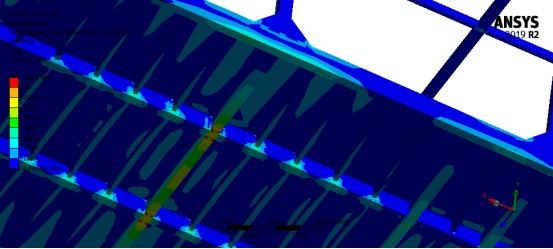
4.2.3 Stress Result - SIE-02
Adjust the stress scale to 0.85 times of RE, that is, 293 MPa. Except for the stress concentration points, the strength requirements are met.
Omitted some similar content and will not repeat it here.
Case 2 - Stress Analysis of Drawer Cabinet Frame Lifting (Showing Partial Content)
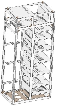
1. Model Establishment
Import the three-dimensional model into SpaceClaim, remove the defects such as interference, chamfers, and interference existing in the model, and remove the parts irrelevant to structural calculation to obtain the finite element calculation model.

2. Material Selection
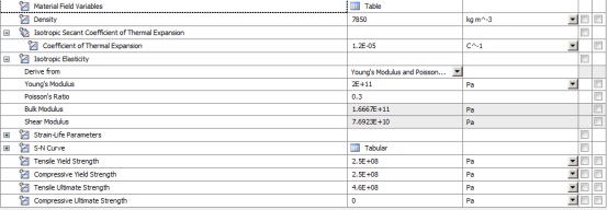
Aluminum-zinc coated steel sheets are selected as materials, and the specific parameters are as follows:
3. Finite Element Mesh Generation
The hexahedral mesh division method is mainly adopted, and the mesh size is set to 10 mm. After division, there are 833,020 nodes and 2,555,491 elements.
<img src="/uploads/allimg/20240428/1-24042Q5163K44.jpg" title="Report on Stress Analysis of Container Lifting (Figure 19)" alt="Report on Stress Analysis of Container Lifting (Figure 19) width="554" height="210"/>
经划分后,网格质量在0.69以上,满足计算精度。

IV. Load Application
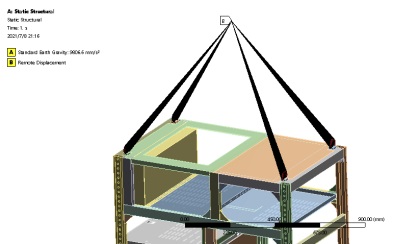
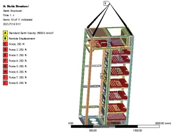
Set up lifting points on the top surface of the model. Connect the lifting points and lifting rings through beams. Considering the self-weight, apply a uniformly distributed load of 250N on each layer.
V. Deformation Results of Finite Element Calculation
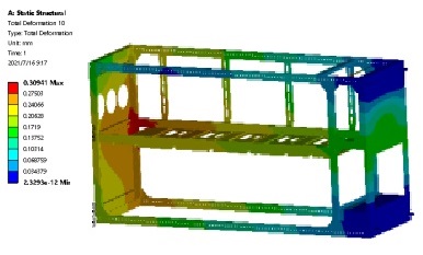

The maximum deformation is 0.3mm, which is located at the lower side of the model and meets the stiffness requirements.
Omitted some similar content and will not repeat it here.
Disclaimer: This article is originally from the official website of Letu Zhizao. Please indicate the source when reprinting.
View More Cases: Heat Dissipation Analysis Thermal Simulation Analysis Die Casting Mold Flow Analysis Modal Analysis CFD Analysis Electromagnetic Field Simulation Analysis Fatigue Analysis CFD Simulation

Leto Intelligent Manufacturing Technology (Suzhou) Co., LTD
199 4191 2022
Business consulting/technical consulting/exchange advice
Scan code wechat consultation, 24 hours to look forward to your voice

