Finite element analysis of a machining machine tool
Simulation Purpose:
For a certain machine tool under development, through CAE analysis research, optimize the layout of the fulcrum positions on the machine tool bed base. Mainly considering the self-weight of the machine tool bed (without considering the structural weight on the upper part of the bed), by adjusting the fulcrum positions, study the deformation situation of the bed, and through analysis, give a relatively reasonable fulcrum support method.
Overview of the Machine Tool:
Figure 1 Layout of the fulcrum positions on the base of a certain machine tool bed (the dark yellow in the figure represents the fulcrum positions)
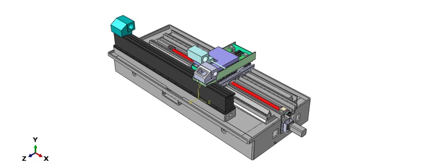
In the analysis and research, the main reference basis is the design drawings of the machine tool bed and the corresponding materials.
Performance Parameters of the Main Material of the Machine Tool
Material | Elastic Modulus (MPa) | Poisson's Ratio | Density (kg/m³) |
Cast Iron | 66178.1 | 0.27 | 7200 |
Mesh Generation:
Using the Abaqus finite element software, the self-weight of the machine tool was analyzed. The model of the machine tool bed is shown in Figure 2. The machine tool bed uses C3D4 elements, and the finite element mesh is shown in Figure 3. In the analysis, the geometric nonlinearity of large deformation was considered.
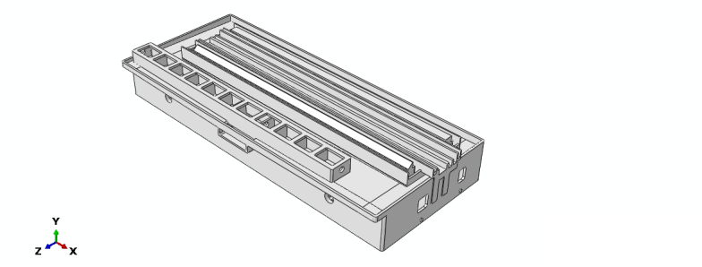
Figure 2 Base of a certain machine tool bed
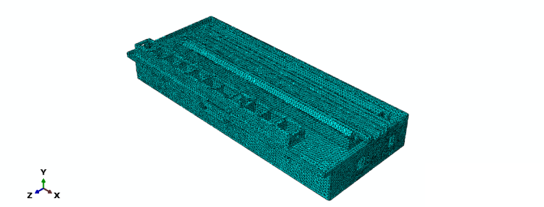
Figure 3 Finite element mesh of the base of a certain machine tool bed
Working Condition 1 - 4 Fulcrums:
When only considering 4 fulcrums (as shown in Figure 4), through finite element analysis, the overall deformation situation of the machine tool under this working condition was given, and the position of the maximum deformation was found (as shown in Figure 5).

Figure 4 Layout of the fulcrum positions on the base of a certain machine tool bed (only 4 fulcrums)
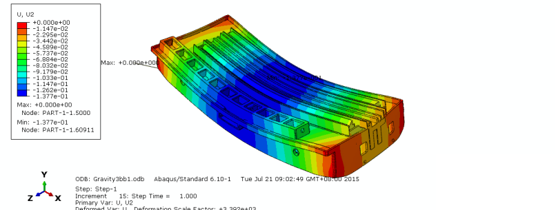
Figure 5, Deformation cloud diagram of the machine tool with 4 fulcrums
Through analysis, it can be seen that when only considering 4 fulcrums, the maximum deformation amount of the machine tool bed reaches 0.1377 mm, and the position of the maximum deformation mainly appears in the middle of the machine tool bed.
Working Condition 2 - 6 Fulcrums:
When only considering 6 fulcrums (as shown in Figure 6), through finite element analysis, the overall deformation situation of the machine tool under this working condition was given, and the position of the maximum deformation was found (as shown in Figure 7).
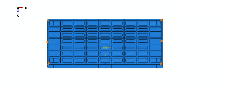
Figure 6 Layout of the fulcrum positions on the base of a certain machine tool bed (only 6 fulcrums)
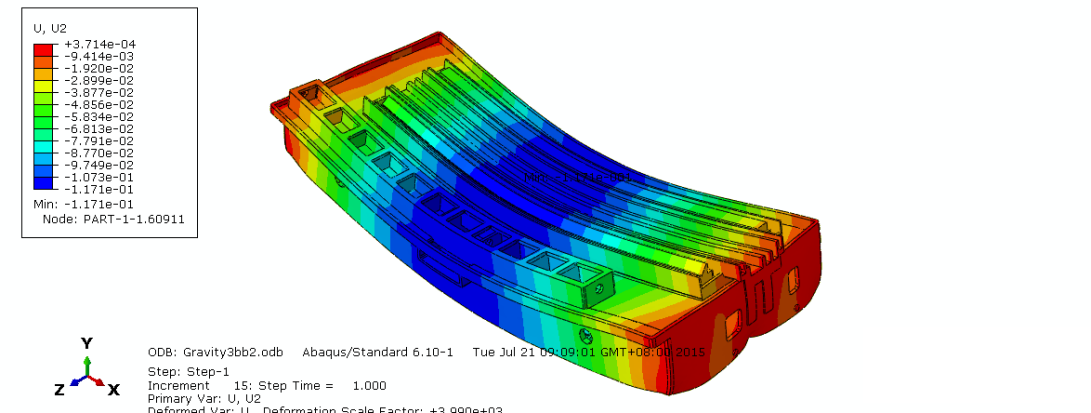
Figure 7 Deformation cloud diagram of the machine tool with 6 fulcrums
Through the finite element analysis of the machining machine tool, it can be seen that when only considering 6 fulcrums, the maximum deformation amount of the machine tool bed can reach 0.1171 mm, and the position of the maximum deformation mainly appears in the middle of the machine tool bed.
Working Condition 3 - 8 Fulcrums:
When only considering 8 fulcrums (as shown in Figure 8), through finite element analysis, the overall deformation situation of the machine tool under this working condition was given, and the position of the maximum deformation was found (as shown in Figure 9).

Figure 8 Layout of the fulcrum positions on the base of a certain machine tool bed (only 8 fulcrums)
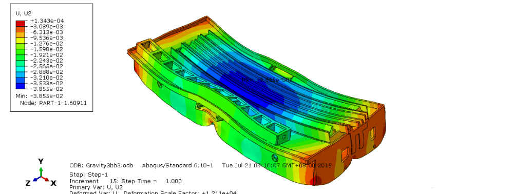
Figure 9 Deformation cloud diagram of the machine tool with 8 fulcrums
Through analysis, it can be seen that when only considering 8 fulcrums, the maximum deformation amount of the machine tool bed can reach 0.03855 mm, and the position of the maximum deformation mainly appears in the middle of the machine tool bed.
Working Condition 4 - 10 Fulcrums:
When only considering 10 fulcrums (as shown in Figure 10), through the finite element analysis of the machining machine tool, the overall deformation situation of the machine tool under this working condition was given, and the position of the maximum deformation was found (as shown in Figure 11).
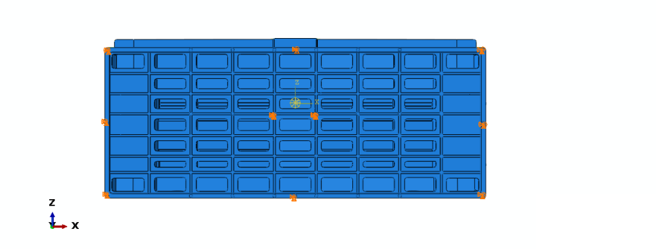
Figure 10 Layout of the fulcrum positions on the base of a certain machine tool bed (only 10 fulcrums)
Through analysis, it can be seen that when only considering 10 fulcrums, the maximum deformation amount of the machine tool bed can reach 0.01847 mm, and the position of the maximum deformation appears in the dark blue area shown in Figure 11.
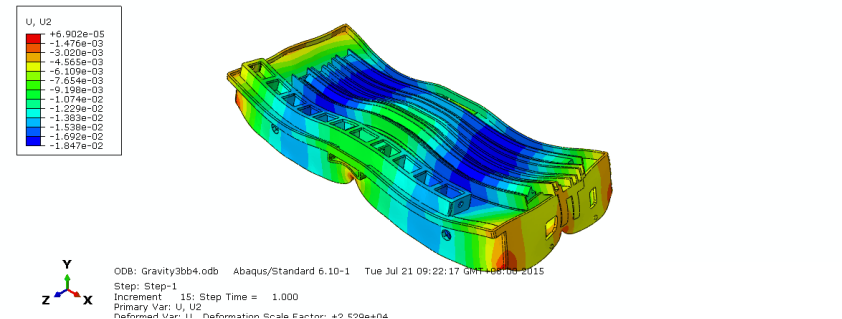
Figure 11 Deformation cloud diagram

图11 10个支点情况下的机床变形云图
Working Condition 5 - 12 Fulcrums:
When only considering 12 fulcrums (as shown in Figure 12), through finite element analysis, the overall deformation situation of the machine tool under this working condition was given, and the position of the maximum deformation was found (as shown in Figure 13).
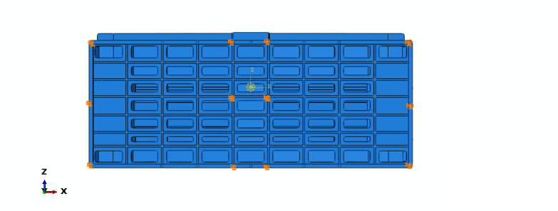
FIG. 12 Position arrangement of fulcrum of a machine tool bed base (only 12 fulcrum, arrangement 1)
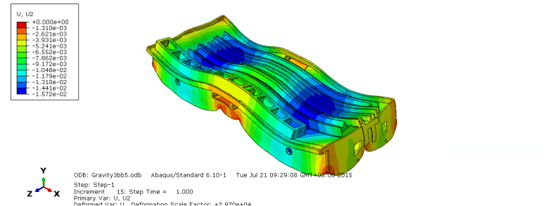
FIG. 13 Machine tool deformation cloud image with 12 fulcrum points (Arrangement 1)
Through analysis, it can be seen that when only considering 12 fulcrums, the maximum deformation amount of the machine tool bed can reach 0.01572 mm, and the position of the maximum deformation appears in the dark blue area shown in Figure 13.
Working Condition 6 - 14 Fulcrums:
When only considering 14 fulcrums (as shown in Figure 14), through finite element analysis, the overall deformation situation of the machine tool under this working condition was given, and the position of the maximum deformation was found (as shown in Figure 15).
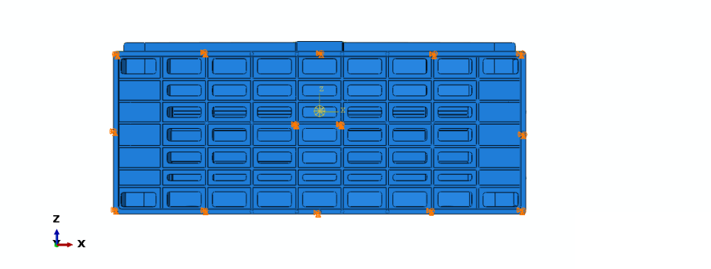
FIG. 14 Position arrangement of fulcrum of a machine tool bed base (only 14 fulcrum)
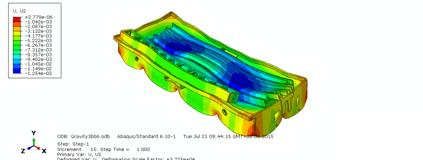
FIG. 15 Machine tool deformation cloud image with 14 fulcrum points
Through analysis, it can be seen that when only considering 14 fulcrums, the maximum deformation amount of the machine tool bed can reach 0.01254 mm, and the position of the maximum deformation appears in the dark blue area shown in Figure 15.
Working Condition 7 - 16 Fulcrums:
When only considering 16 fulcrums (as shown in Figure 16), through finite element analysis, the overall deformation situation of the machine tool under this working condition was given, and the position of the maximum deformation was found (as shown in Figure 17).
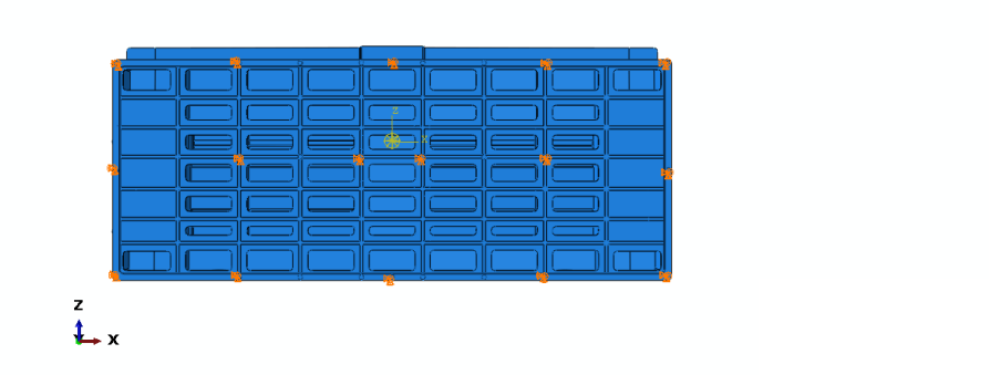
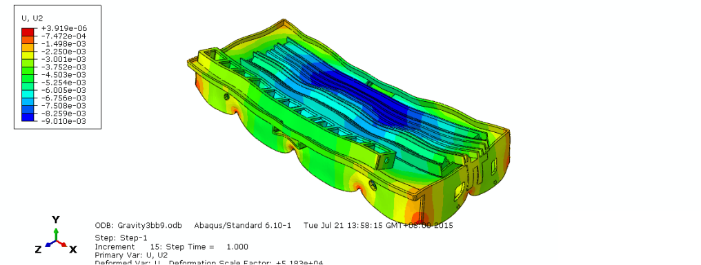
FIG. 17 Machine tool deformation cloud image with 16 fulcrum points
Through the finite element analysis of the machining machine tool, it can be seen that when only considering 16 fulcrums, the maximum deformation amount of the machine tool bed can reach 0.00901 mm, and the position of the maximum deformation appears in the dark blue area shown in Figure 17.
Conclusion:
From the above finite element analysis of the machining machine tool bed, it can be seen that the more fulcrums are arranged, the better the deformation of the machine tool bed can be controlled. However, in reality, it is usually hoped to use the least number of fulcrums to control the deformation amount of the bed within a reasonable range. According to the allowable deformation standard of the bed, a suitable fulcrum layout can be selected, and the fulcrums should be placed at the intersection positions of the reinforcing ribs as much as possible.

Leto Intelligent Manufacturing Technology (Suzhou) Co., LTD
199 4191 2022
Business consulting/technical consulting/exchange advice
Scan code wechat consultation, 24 hours to look forward to your voice

