Heat dissipation analysis of liquid-cooled energy storage battery cabinet PACK
```html
Business Content:
Undertake thermal simulation analysis and structural design optimization for container energy storage and industrial and commercial energy storage battery cabinets. Have provided services for more than 50 energy storage enterprises. Contact Manager Xu at 199 4191 2022.
Value of Heat Dissipation Analysis:
Energy storage heat dissipation simulation technology refers to using computer technology to simulate and model energy storage systems to verify the feasibility, stability, efficiency, economy and other indicators of energy storage solutions. Through heat dissipation simulation technology, the performance and behavior of energy storage systems can be predicted quickly and accurately, problems can be discovered and optimization solutions can be found, thus reducing the actual operating costs, improving the service life and efficiency of equipment, and also reducing the workload and costs of experiments and tests. Currently, energy storage technologies cover various forms of energy storage, such as electrochemical energy storage, mechanical energy storage, thermal energy storage, etc., and are widely used in fields such as energy reserves, peak shaving and valley filling, self-provided power supplies, and emergency backup.
Heat Dissipation Analysis Cases
Case 1: Heat Dissipation Simulation of Air-cooled Battery Packs
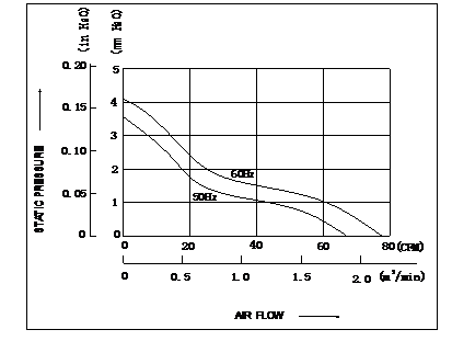
There are 3 axial flow fans installed on the back of the battery pack, with the model number BT12025B2H. The rated rotational speed is 2,000 RPM, the air volume is 1.87 m³/min (66 CFM), and the wind pressure is 3.56 mmH₂O. The figure shows the fan performance curve graph, and the following figure shows the simulation analysis model diagram of the battery pack.
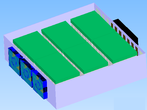
According to the relevant parameters in the table, which are the values set during the simulation analysis modeling, the size of the battery cells and the bracket housing are modeled at a 1:1 scale. The heat loss of a single battery pack is 38.4 W, which is evenly distributed among each battery cell.
Thermal Simulation Results of Battery Packs:
The following figure shows the residual curve of the pack simulation analysis and the temperature curve of the monitoring points.
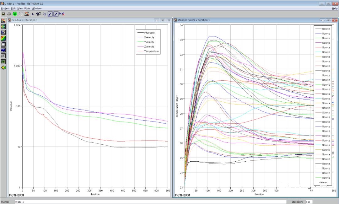
The thermal simulation software for the pack is used to solve the residual curve for the entire battery pack and each battery cell monitoring point. The results show that the monitoring temperature curve of the battery pack finally tends to be stable, and the simulation results converge.
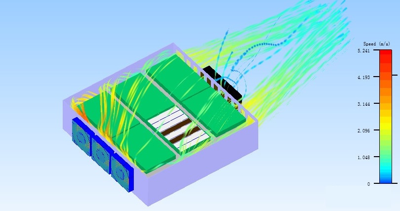
The following figure shows the velocity streamline particle diagram of the pack.
Temperature Cloud Diagram of Battery Packs
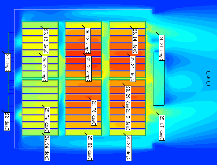
Judging from the temperature cloud diagram, when the air supply temperature of the air conditioner is 22 °C, the temperature of the front-end battery cells is about 25 °C, the temperature of the middle battery cells is relatively high, with the highest temperature being about 30.7 °C, and the temperature of the rear-end battery cells is about 30 °C at the highest. The temperature of the battery cells on both sides is lower, and that of the middle ones is higher. This should be caused by the higher air flow velocity on both sides and the lower flow velocity in the middle, which can be judged from the velocity cloud diagram in Figure 1.5 and the particle diagram in Figure 1.6 below.
Velocity Cloud Diagram of Battery Packs
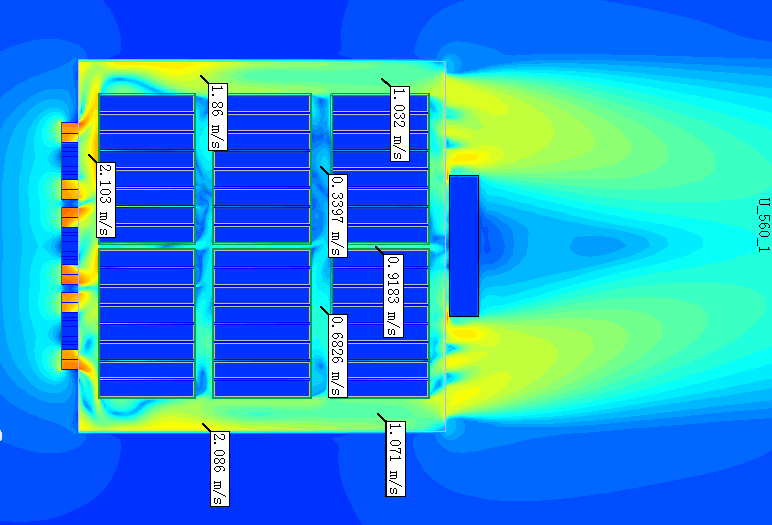
Analyzing from the temperature cloud diagram, velocity cloud diagram and other simulation results, the ventilation gap between the battery cells is very narrow, resulting in large ventilation resistance. There is a relatively large gap between the battery cells on both sides and the sheet metal housing, and the air leakage problem is quite obvious. The effective ventilation is relatively insufficient, and it is necessary to add wind-blocking structures.
Conclusions and Recommendations
This project simulates the maximum load working condition of the containerized energy storage battery system at 40 °C (the extreme external environmental temperature for use). Through the finite element simulation data and the internal temperature distribution cloud diagram of the equipment, the temperature field cloud diagram of the internal battery system of the energy storage system at an external environmental temperature of 40 °C can be intuitively understood. It can be concluded that the temperature control system of the thermal design of this project fully meets the temperature requirements of the lithium battery system under the 0.5C charge and discharge working condition and has a relatively high margin. In order to enable the energy storage battery system to work for a long time in harsh environments, the following suggestions are put forward for the product design of this energy storage system: Add wind-blocking structures on both sides inside the battery pack to increase the ventilation volume flowing through the battery cells; If there is space on the front side of the battery pack, it is recommended to place the fan in the front and change to exhaust heat dissipation, and only one fan needs to be installed.
Case 2 - Thermal Analysis of the Whole Industrial and Commercial Energy Storage Cabinet - Liquid Cooling Unit
The physical model adopts the Reynolds-averaged method and the VOF (Volume of Fluid) model to simulate the gas-liquid two-phase turbulent process of the refrigerant when it enters the cold plate. The grid division uses the unique thin body grid and expert optimization functions of StarCCM+ to conduct fine grid division for the inside of the cold plate.

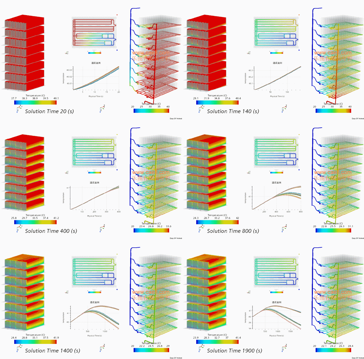
Thermal Design Requirements for Energy Storage Battery Systems
1. Total heat generation of the battery pack when one cycle is completed:
Q (heat generation) = 0.0384 kW × 4 h × 3600 ≈ 552.96 kJ
The total heat generation will be divided into two parts. One part is converted into the temperature rise of the battery pack's own materials, and the other part is dissipated to the outside of the battery pack through the heat dissipation design of the battery, and this part of the heat is the minimum cooling capacity required by the air conditioner.
The composition and characteristics of various materials in the battery pack are shown in the following table:
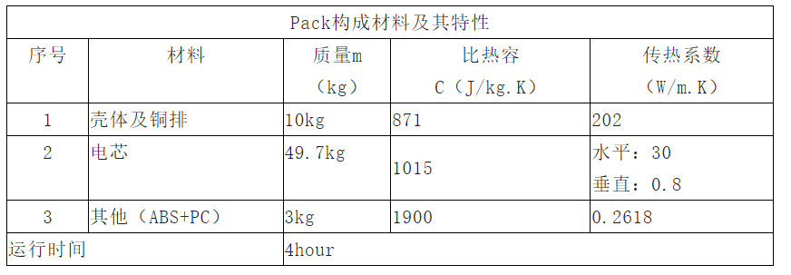
The mass proportion of structural parts other than the battery cells is very small, and the temperature rise is also small. They can be ignored as design margins during calculation. During the actual measurement of the module, the average temperature rise of the battery cells in one cycle is 5 °C.
2. Heat absorbed by the battery pack in one cycle:
Q (absorption) = cmΔT = 1015 × 49.7 × 5 ≈ 252.22 kJ
3. Minimum cooling power required by the air conditioner for the entire container battery:
Q (air conditioner) = (Q (heat generation) - Q (heat absorption)) × 38 (modules) × 10 (clusters) / 4 (h) × 3600 ≈ 7.9 kW
In addition, when selecting the air conditioner, it is also necessary to comprehensively consider the external environmental temperature of the container, the thermal insulation performance of the container itself, etc., and it is necessary to consider the heat leakage of the box: Q (leakage) = K × A × ΔT = 5.5 × 114.4 × 15 = 9.4 kW
K: comprehensive heat transfer coefficient; ΔT: temperature difference between the inside and outside of the container, considered as 15 °C; A: surface area of the container
<p style="text-wrap: wrap; margin-top: 5px; margin-bottom: 5px;

Leto Intelligent Manufacturing Technology (Suzhou) Co., LTD
199 4191 2022
Business consulting/technical consulting/exchange advice
Scan code wechat consultation, 24 hours to look forward to your voice

