Thermal Simulation Analysis of Air-cooled Energy Storage Battery Containers
Business Content:
Thermal simulation analysis and structural design optimization for container/industrial and commercial energy storage. Have provided services for more than 50 energy storage enterprises. Contact Manager Xu at 199 4191 2022.
Main Simulation Types of Energy Storage:
Large-scale Energy Storage: Containerized energy storage systems. Medium/Small-scale Energy Storage: Industrial and commercial energy storage, household energy storage.
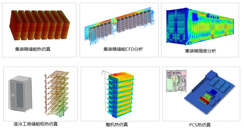
1. Analysis of heat dissipation during the charge and discharge cycle of the energy storage battery system: The temperature of the battery cells should not exceed a certain threshold, and the temperature difference should be less than a certain value.
2. CFD Simulation: Air duct design for air-cooling systems, pipeline design for liquid-cooling systems; pressure loss and flow velocity design.
3. CAE Analysis: Static load simulation, lifting simulation, transportation simulation, vibration simulation, impact simulation, etc.
Case 1: Thermal Simulation of Energy Storage Battery Containers
On both sides of the container, each cluster of batteries is provided with cooling and heat exchange by two integrated machines with rated cooling capacity. The air conditioner is connected to the battery clusters through the top air cap and the back air duct. Through the isolation of hot and cold air, the precise purpose is achieved. This design is currently a relatively mainstream form of air duct structure.
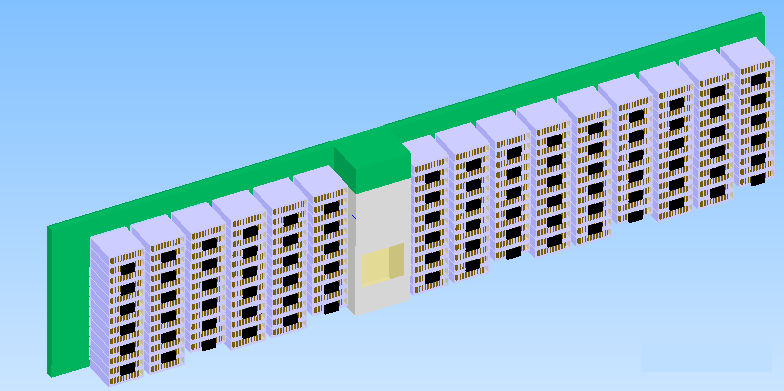
120*25 Since the battery systems on both sides of the container have the same configuration and are isolated by hot and cold air, the thermal simulation models on both sides are the same. Therefore, it is only necessary to conduct thermal simulation on the single-sided energy storage battery system. Figure 1.8 below is the simulation analysis model diagram of the single-sided energy storage battery system.
Simulation Analysis Model Diagram of One Side of the Container
Simulation Purpose
During the product research, development and design process of the energy storage system, thermal simulation analysis software can relatively realistically simulate the thermal distribution status of the system. Conducting thermal simulation analysis on the product in the product design stage can accurately locate the temperature in the model. By modifying the model or taking necessary improvement measures, problems with poor thermal design can be eliminated. Reasonably using thermal simulation analysis software for thermal design can improve the success rate of the product's first design, thereby shortening the R&D cycle and reducing R&D costs.
Project Site Environment
The local area has relatively hot summers and relatively low temperatures in winter. By querying the weather data of Dantu, Danyang, Jurong, Runzhou, Yangzhong and other regions in Zhenjiang City, Jiangsu Province in the past 5 years, the environmental temperature is -10℃ to 40℃. The battery cells adopt lithium iron phosphate batteries; the internal design of the battery consists of several battery cells connected in parallel and series; each cluster of battery racks is designed with several batteries connected in series. There are a total of several clusters of battery racks in the entire high-cube container. The layout diagram is shown in the figure below.

Simulation Conditions
1. Operating Conditions: The operating condition of the energy storage system is a continuous charge and discharge cycle at a 0.5C rate.
2. This analysis report only conducts thermal simulation analysis on the battery compartment of the 40 energy storage system.
Calculation of Heat Generation
The heat generation Q1 of a single battery cell during the 0.5C charge and discharge process is 0.8W.
The heat generation Q2 of a single battery pack = Q1 × 48 = 38.4W.
The heat generation Q3 of a single battery rack = Q2 × 38 = 1459.2W.
The total heat generation Q of the entire container = Q3 × 10 = 14.59kW.
Some Thermal Simulation Results
Figure of the single-sided velocity cloud diagram of the container.
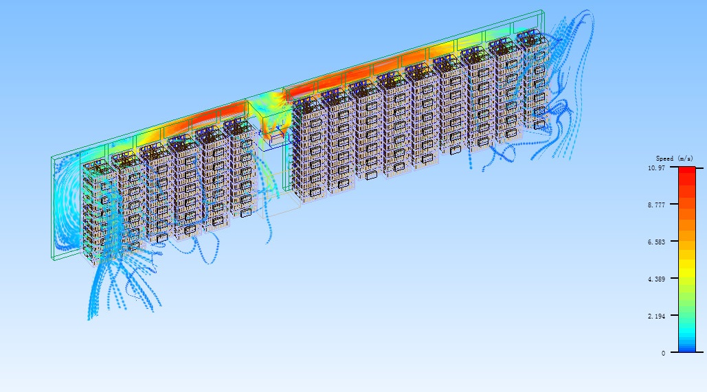
Figure of the single-sided temperature cloud diagram of the container.

The thermal simulation software is applied to conduct simulation operations on the single-sided energy storage battery system in the container. Figures 1.9 and 1.10 below are the velocity cloud diagram and temperature cloud diagram of the single-sided energy storage system respectively. The results show that the thermal design of this energy storage system scheme meets the requirements.
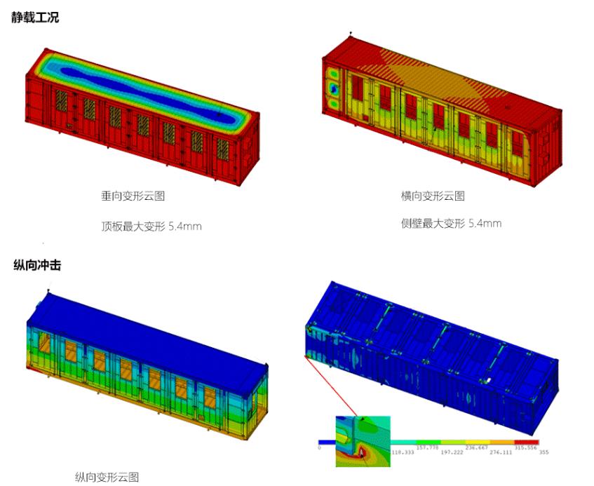
Simulation Results of Container Strength
From the simulation analysis results, it can be seen that the bottom sealing plate has punctate yielding (iron-gray), which is caused by stress concentration. The safety of the structure can be evaluated and judged by comprehensively considering the functional requirements of the equipment.
Case 2: Air-cooling Heat Dissipation Analysis of Containerized Energy Storage Systems
The containerized energy storage system is composed of several lithium batteries closely arranged. When the energy storage system is charging and discharging, the batteries inside the system will generate a large amount of heat. Due to the relatively close arrangement and small gaps of the lithium batteries, it is difficult for the heat generated by the batteries to be quickly discharged, and phenomena such as heat accumulation between battery groups and large operating temperature differences will occur.
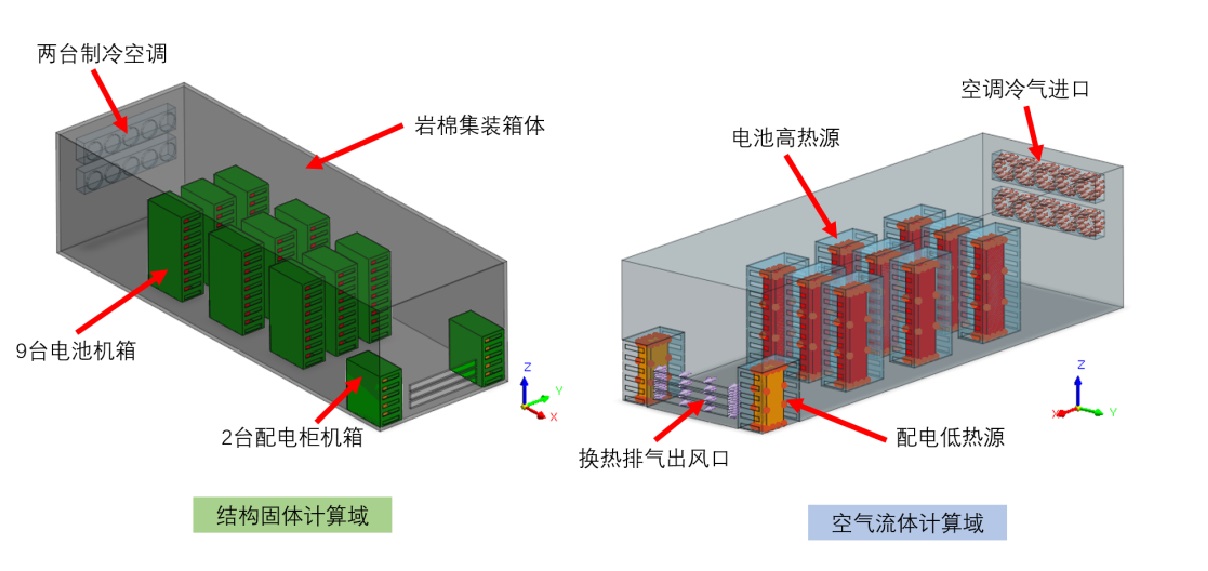
This case uses the NFX CFD heat dissipation analysis module and utilizes the fluid-solid conjugate heat transfer function to calculate the battery temperature rise process of the containerized energy storage system, and analyzes the ventilation efficiency inside the container and the convective heat dissipation characteristics inside the system.


In this calculation, the main components considered for the containerized energy storage system are the rock wool container body. The box is a cuboid container with dimensions of 10.6m × 3.5m × 2.8m, 9 battery units, and 2 distribution cabinet chassis. Constant temperature rise heat sources are considered in the battery units and distribution cabinet chassis. The batteries are simplified as cuboid heat sources with a volume of 0.27m³, and a heat source with a volume of 0.165m³ is considered in the distribution cabinet. The one-click fluid domain extraction function in NFX is utilized.
Other Thermal Simulation Cases
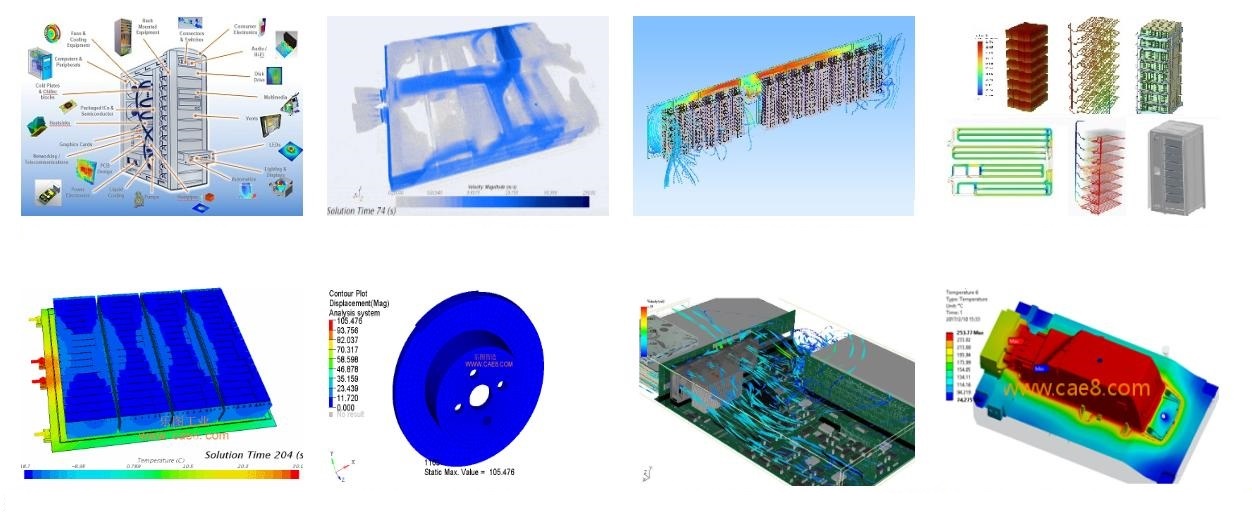
Undertake thermal simulation analysis, heat transfer analysis, heat dissipation analysis, solar thermal radiation analysis, involving industries such as chip semiconductors, electronic appliances, medical devices, and automobiles.

Leto Intelligent Manufacturing Technology (Suzhou) Co., LTD
199 4191 2022
Business consulting/technical consulting/exchange advice
Scan code wechat consultation, 24 hours to look forward to your voice

