CAE Topology Optimization: A Gospel of Product Design Optimization
With the continuous development of science and technology, the position of product research and development in its life cycle is becoming increasingly important. Different R & D processes have a significant impact on the product's development cycle and cost.
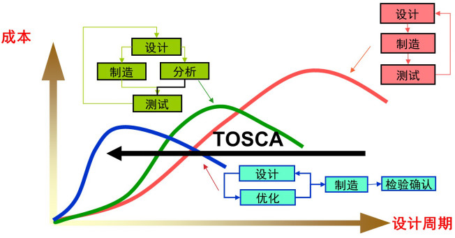
The above figure depicts the impact of different R & D processes on the design cycle and cost. The abscissa represents the design cycle, and the ordinate represents the R & D cost.
The red curve represents:
The R & D process of traditional products, which involves design - manufacturing prototypes - testing, adjusting the design scheme according to the test results, and then remanufacturing prototypes for testing. In this process, tests are used to guide design modifications, prototype manufacturing, and testing.
The green curve represents:
In order to accelerate the product's design cycle, finite element analysis technology is widely applied in product R & D. For the completed design model, while manufacturing the prototype, finite element analysis is first carried out according to the stress condition of the product. Then, the design parameters are adjusted according to the analysis results, and finite element calculations are carried out again. After multiple calculations, analyses, and design adjustments, the prototype is manufactured and tested, and finally, a suitable design model is obtained.
The blue curve represents:
The previous analysis and scheme adjustments are also manually intervened, which is closely related to the design experience of designers. In order to achieve automatic product design optimization, software such as TOSCA and ISIGHT is introduced for optimization during the design and analysis process. According to the defined objective function and constraint conditions, the optimization of the model scheme can be automatically completed, significantly reducing the R & D cost and shortening the design cycle.
Topology optimization can be divided into the following categories:
1. Classical topology optimization
2. Contact nonlinear topology optimization
3. Fatigue nonlinear topology optimization
4. Typical shape optimization
5. Nonlinear dynamic analysis shape optimization
6. Fatigue shape optimization
7. Stripe optimization
8. Internal flow field topology optimization
9. Sound field topology optimization
And so on. The optimization process ideas are similar. The following is an overview from the aspects of topo, fatigue optimization, and shape optimization.
Classical topo optimization scheme
Classical topology optimization is widely used in the structural design process and can quickly and efficiently obtain the initial design scheme from the design space.
The common optimization process is as follows:
1. Import the CAD model from CAD software (Pro/E, CATIA, UG, SolidWorks, etc.).
2. Use pre- and post-processing tools such as ANSA for finite element analysis pre-processing.
a) Geometry cleaning, meshing
b) Material setting, assembly connection, setting analysis steps
c) Setting boundary conditions and loads
d) Model checking and outputting/inputting files
3. Set TOSCA optimization pre-processing.
a) Set the optimization algorithm, design area, and response variables.
b) Set the optimization objective and constraints.
c) Set the stop condition, optimization settings, and smooth parameters.
4. Select a finite element solver (ABAQUS, NASTRAN, ANSYS, MARC…), submit the calculation. The optimization software automatically calls the finite element solver and automatically calls the TOSCA optimization solver for optimization calculation, and judges whether it converges or reaches the stop condition. If not, continue the calculation of the next cycle. If satisfied, end the optimization calculation.
5. Use TOSCA.Smooth and TOSCA.Post to smooth the mesh and view the optimization results.
6. Output the verification model to the solver to verify and calculate again.
7. Output files supported by CAD, such as IGS and STEP, to CAD software for reference in design.
The following is an optimization case of an automobile part:
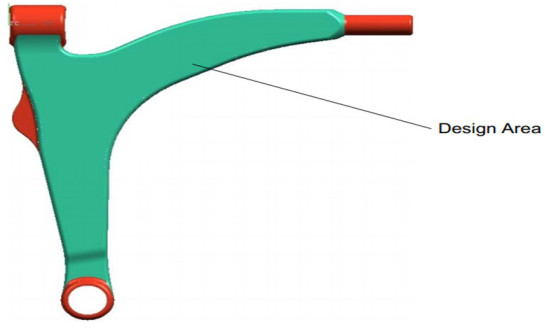
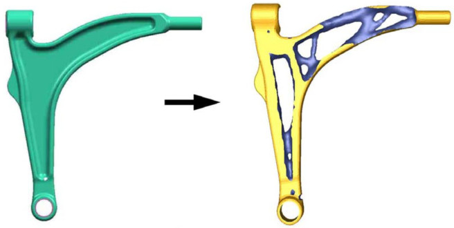
The red areas are the loading and constraint positions; the green area is the optimizable area. A fixed constraint is applied at the upper left red position; the shaft center in the lower left red area is subjected to a tensile force of 1000 KN in the 45° direction; the red area on the right is connected to a rubber bearing. The entire structure is symmetrical about the XY plane, and the processing method of the model is casting. The optimization objective is to reduce the volume by 30% while maximizing the structural stiffness.
Fatigue Nonlinear Topology Optimization
Compared with classical topology optimization, fatigue nonlinear topology optimization requires further calculation of fatigue life analysis (damage), which is equivalent to adding a fatigue calculation step to classical topology optimization. The software tools used include: 3D CAD modeling software --- ANSA/meta pre- and post-processing platforms --- optimization platforms such as TOSCA --- finite element solver software such as ABAQUS --- fatigue calculation tools such as FE/SAFE. All links are closely connected to achieve automatic driving and control, enabling rapid acquisition of optimization results.
The following is a fatigue nonlinear topology optimization process:
1. Import the CAD model from CAD software (Pro/E, CATIA, UG, SolidWorks, etc.).
2. Use pre-processing tools such as ANSA to perform pre-processing for finite element analysis.
a) Geometry cleaning, meshing
b) Material setting, assembly connection, setting analysis steps
c) Setting boundary conditions and loads
d) Model checking and outputting/inputting files
e) According to the results of the preliminary calculation, perform fatigue pre-processing settings in the fatigue software.
3. Set TOSCA optimization pre-processing.
a) Set the optimization algorithm, design area, and response variables.
b) Set the optimization objective and constraints.
c) Set the stop condition, optimization settings, and smooth parameters.
4. Select a finite element solver (ABAQUS, NASTRAN, ANSYS, MARC…), submit the optimization calculation, and the optimization software will automatically call the finite element solver.
5. Automatically call the fatigue solver to calculate fatigue failure.
6. Automatically call the TOSCA optimization solver to perform optimization calculation and judge whether it converges or reaches the stop condition. If not, return to step 4 to perform the next cycle calculation of the finite element solution. If satisfied, end the optimization calculation.
7. Use TOSCA.Smooth and TOSCA.Post to smooth the mesh and view the optimization results.
8. Output the verification model to the solver to verify and calculate again.
9. Output files supported by CAD, such as IGS and STEP, to CAD software for reference in design.
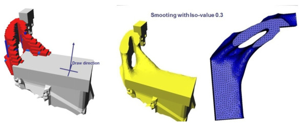
The following is the optimization result of a certain engine part:
Shape Optimization
The biggest feature of shape optimization is that it integrates two optimizations involved in a complete optimization analysis into one optimization task. It uses topology optimization to obtain the initial configuration and then uses shape optimization to refine the local areas. It is widely used in actual product design. The calculation tools involved include: 3D CAD modeling software --- ANSA/meta pre- and post-processing platforms --- optimization platforms such as TOSCA --- finite element solver software such as ABAQUS. All links are closely connected. By setting on a unified platform, automatic driving and control can be achieved, and optimization results can be obtained quickly.
The following is a typical topology - shape optimization process:
1. Import the CAD model from CAD software (Pro/E, CATIA, UG,
SolidWorks, etc.).
2. Use pre-processing tools such as ANSA to perform pre-processing for finite element analysis.
a) Geometry cleaning, meshing
b) Material setting, assembly connection, setting analysis steps
c) Setting boundary conditions and loads
d) Model checking and outputting/inputting files
e) According to the results of the preliminary calculation, perform fatigue pre-processing settings in the fatigue software.
3. Set TOSCA optimization pre-processing.
a) Set the optimization algorithm, design area, and response variables.
b) Set the optimization objective and constraints.
c) Set the stop condition, optimization settings, and smooth parameters.
4. Select a finite element solver (ABAQUS, NASTRAN, ANSYS, MARC…), submit the optimization calculation, and the optimization software will automatically call the finite element solver.
5. Automatically call the TOSCA optimization solver to perform optimization calculation and judge whether it converges or reaches the stop condition. If not, return to step 4 to perform the next cycle calculation of the finite element solution. If satisfied, end the optimization calculation.
6. Output the verification model to the solver to verify and calculate again. If the results meet the requirements, directly output the IGS model to guide the design.
7. If there is local stress concentration, jump to the shape optimization step and set TOSCA shape optimization pre-processing.
8. Automatically call the TOSCA optimization solver to perform optimization calculation and judge whether it converges or reaches the stop condition. If not, return to step 4 to perform the next cycle calculation of the finite element solution. If satisfied, end the optimization calculation.
9. Use TOSCA.Smooth and TOSCA.Post to smooth the mesh and view the optimization results.
10. Output files supported by CAD, such as IGS and STEP, to CAD software for reference in design.
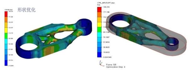
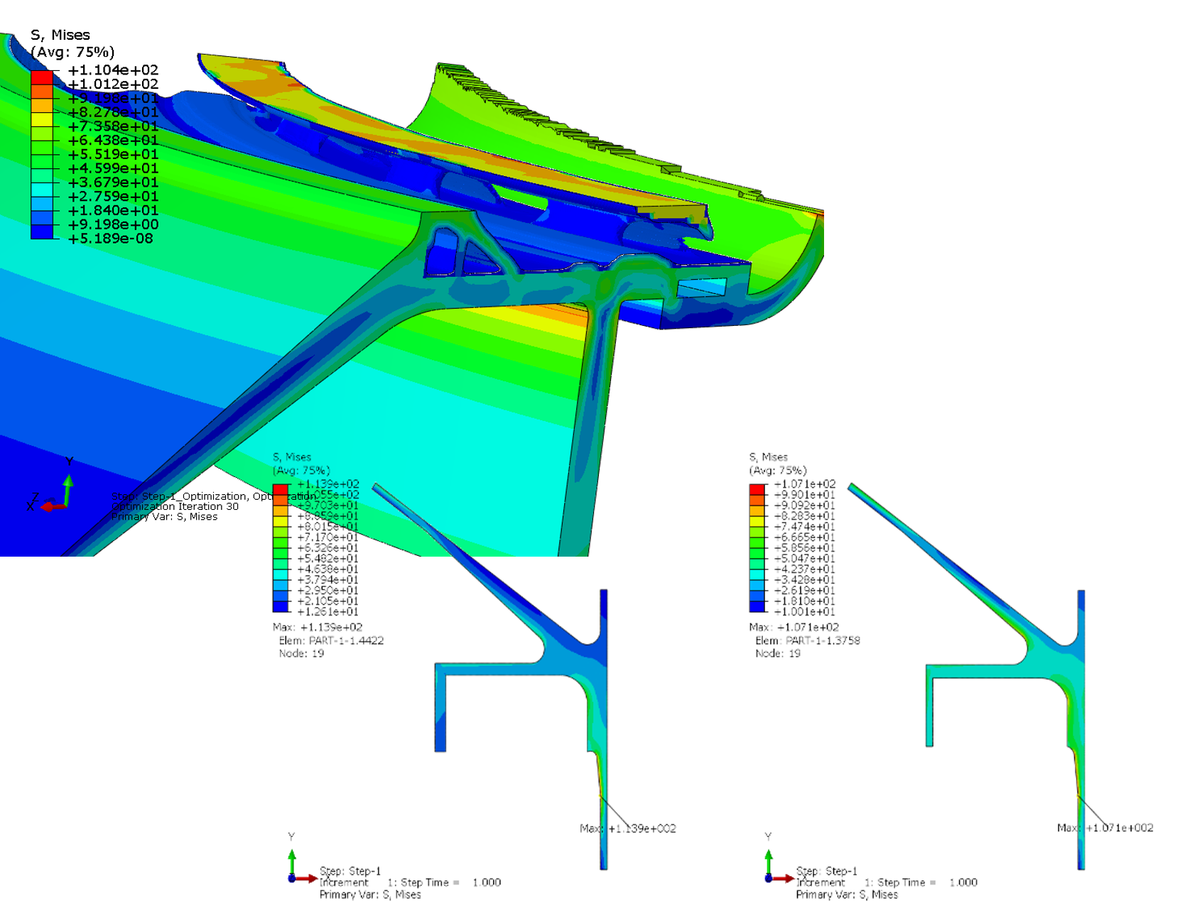
For shape optimization, calculate and solve the verification model output above, and then redefine the shape optimization. Define minimizing the maximum stress in the design area as the optimization objective. The results are as follows:
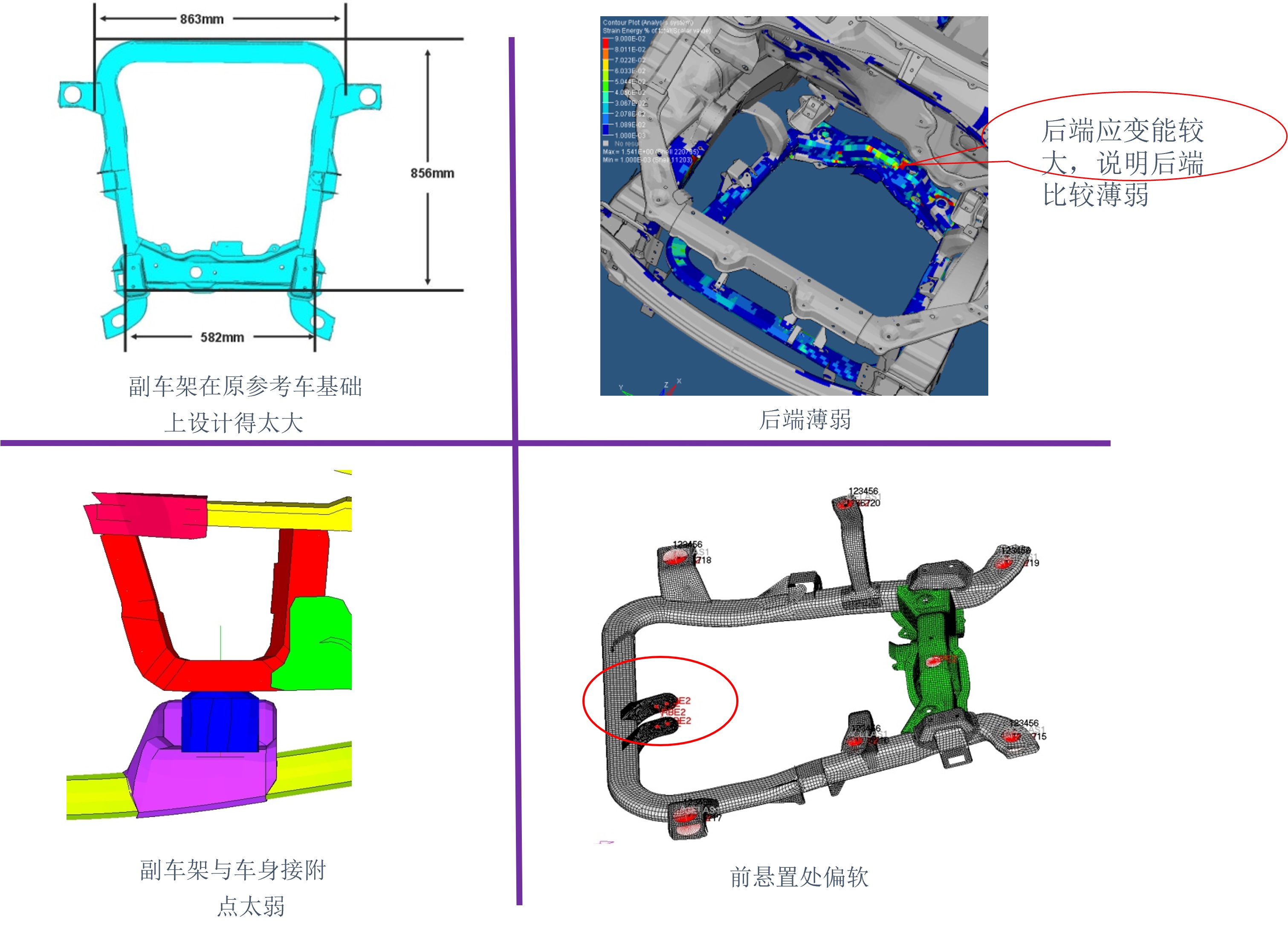
Optimization of the Sub-frame --- Based on Dassault ABAQUS + ATOM
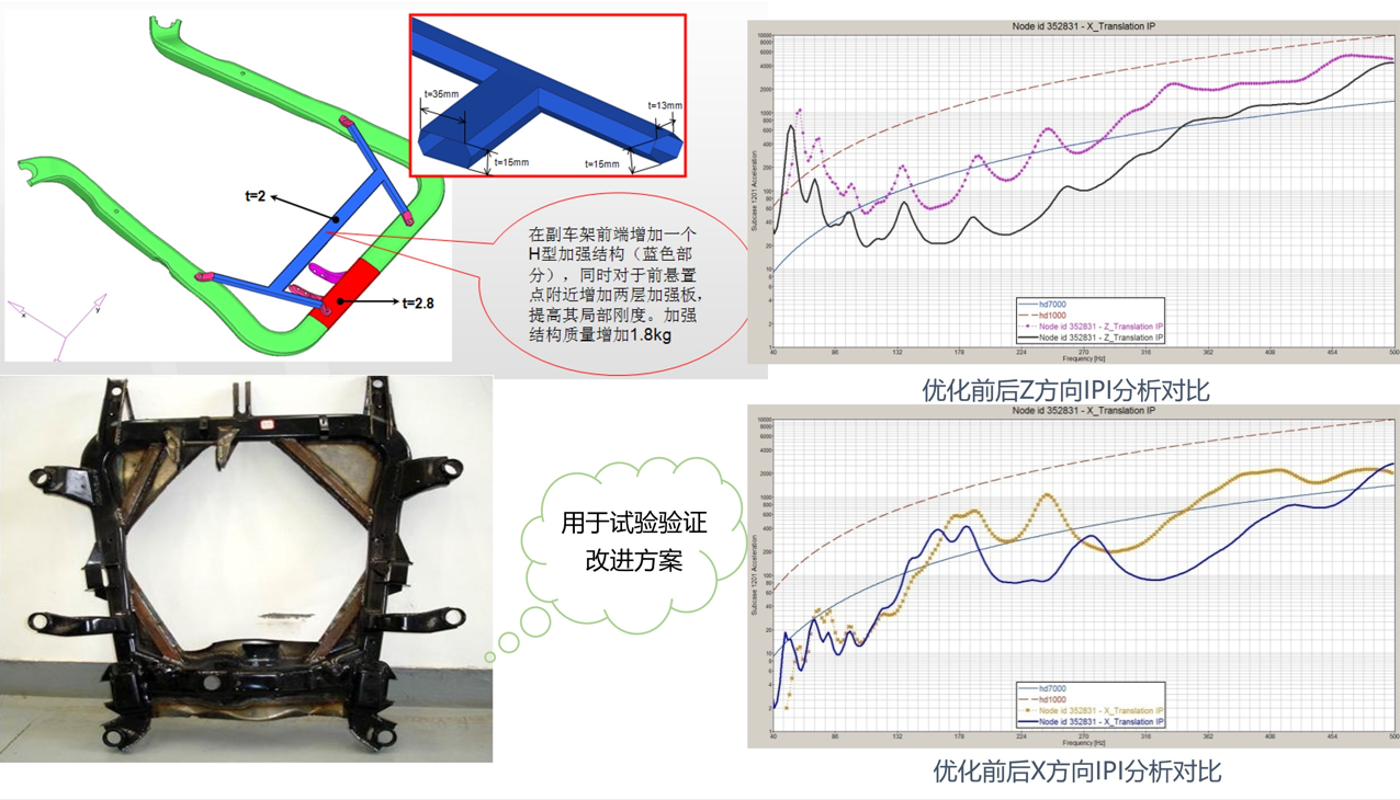
Analysis and Local Optimization of the Frame of Commercial Passenger Vehicles
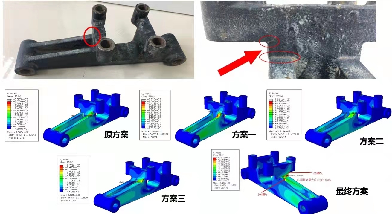
Finite Element Analysis for the Lightweight Design of a Certain Aerospace Equipment
There are three modeling methods: axisymmetric model, solid model, and shell model; strength, stiffness, and modal analysis; instantaneous impact analysis; optimization analysis of the main structural parameters; topology optimization analysis of key parts; significant weight reduction effect.

Leto Intelligent Manufacturing Technology (Suzhou) Co., LTD
199 4191 2022
Business consulting/technical consulting/exchange advice
Scan code wechat consultation, 24 hours to look forward to your voice
